Heat pump basics · Cycles
Refrigeration & heat-pump cycle guide
Before you pick a compressor or refrigerant, you need a cycle family. This illustrated guide maps ideal references (reverse Carnot), gas cycles (reverse Brayton), the industry workhorse (subcritical vapor compression) and its upgrades, transcritical CO₂, absorption, and open steam/MVR—with flow, P–h, and T–s reading tips. Pair with Fundamentals Part 2 (why ΔT forces variants) and the homepage HTHP configs (a)–(i).
0 · Cycle families & how to read the charts
Cycles are the system grammar. Components (compressor, HX, valves) are vocabulary—you need both. Start here so later chapters share one map.
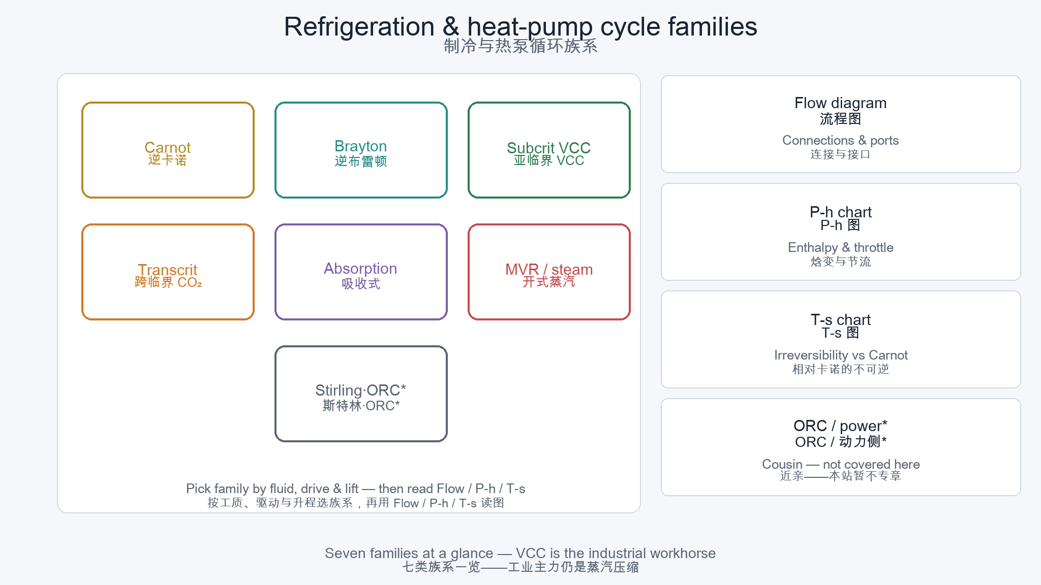
Flow diagram
Shows what connects to what: compressors, heat exchangers, expanders/valves, vessels. Best for plant conversation and P&ID intuition.
P–h diagram
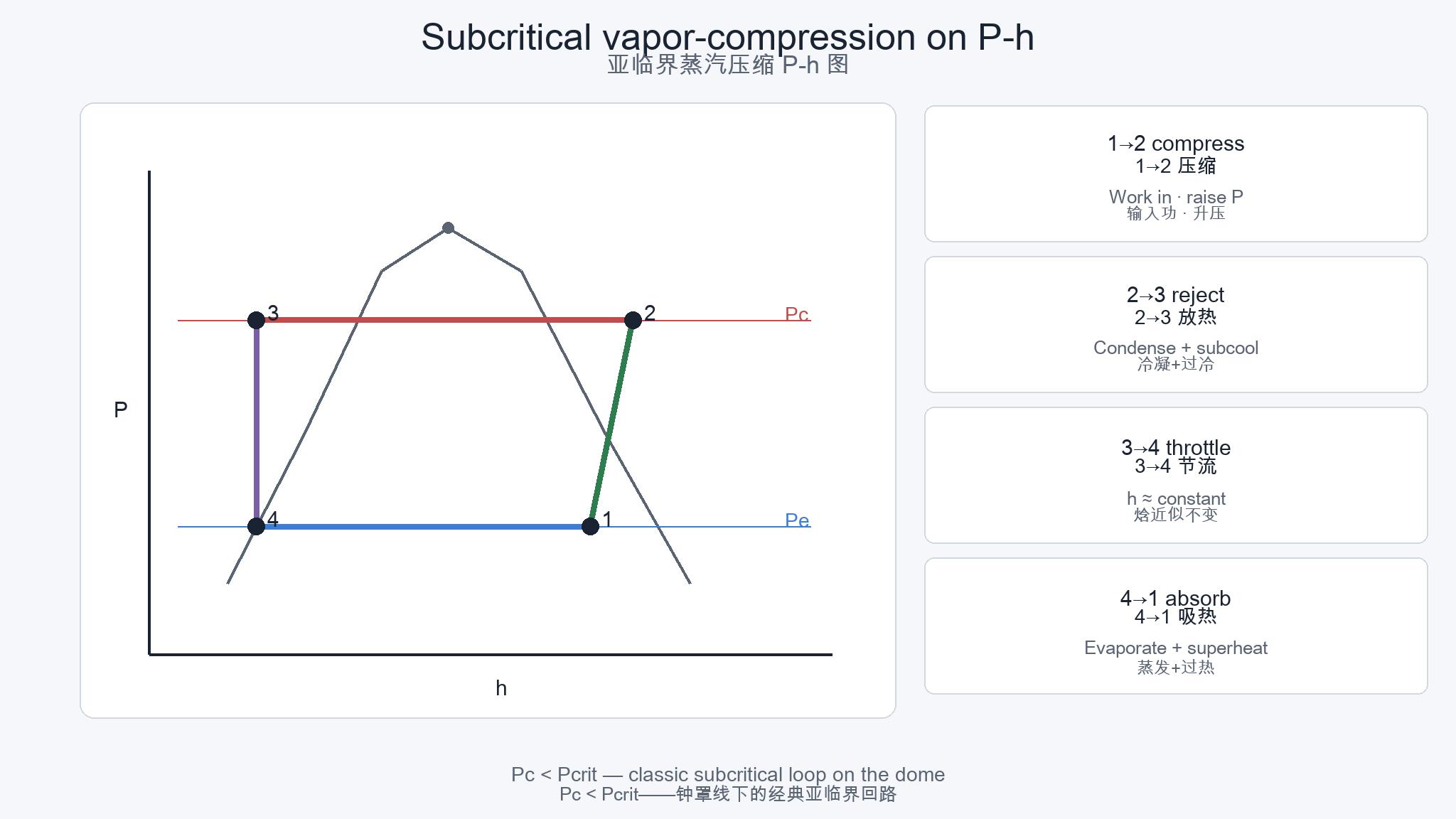
Pressure vs enthalpy. Read capacity and power as Δh, see throttle as nearly vertical (h≈const), and spot subcooling / superheat. Default language for VCC and CO₂ packs. Check a single-point state on the property calculator.
T–s diagram
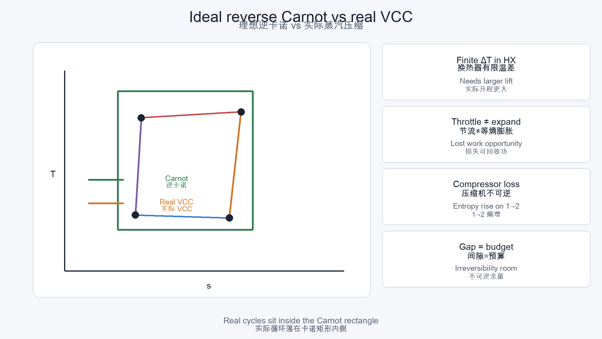
Temperature vs entropy. Best for Carnot distance and irreversibility—why real cycles cannot fill the ideal rectangle.
Same physics, different “useful” side
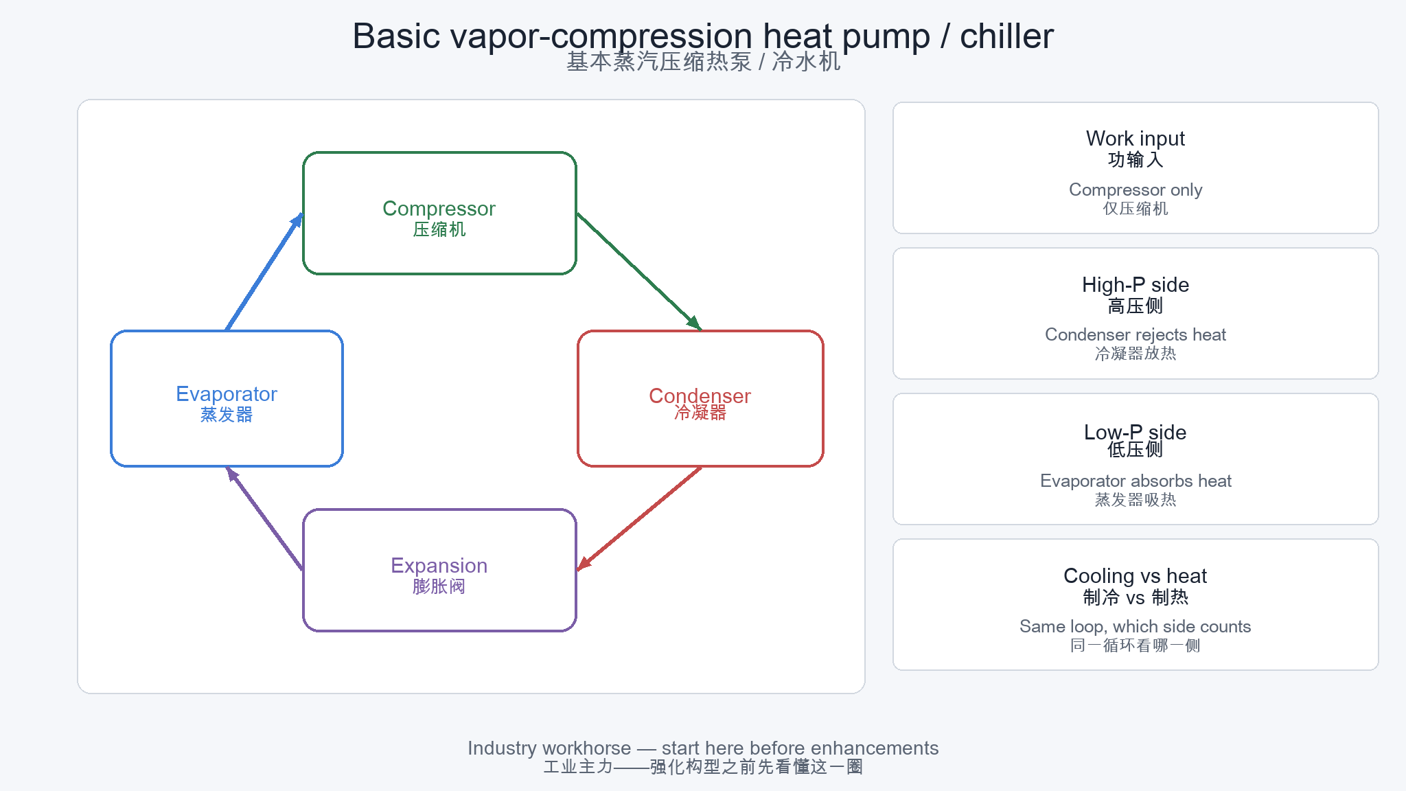
A chiller and a heat pump can share the same vapor-compression loop. Cooling counts evaporator kW; heating counts condenser (or gas-cooler) kW. Always state source and sink.
1 · Reverse Carnot — the theoretical ceiling
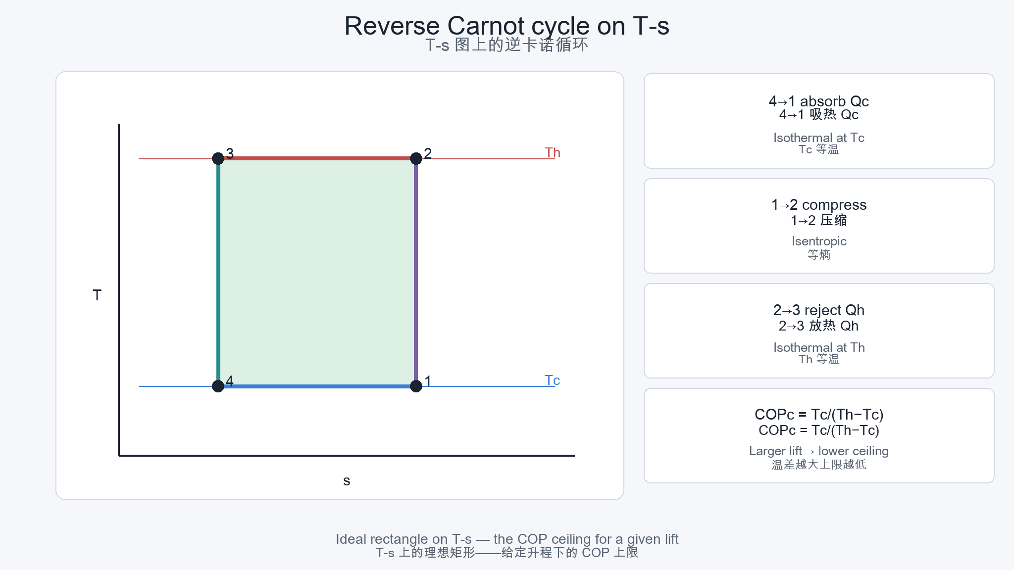
Reverse Carnot is not a machine you buy. It is the upper bound on COP for given cold and hot temperatures—and the reason large lift forces different real cycles.
COP intuition
Cooling: COPc = Tc / (Th − Tc). Heating: COPh = Th / (Th − Tc) (absolute temperatures). Larger lift → lower ceiling—no marketing brochure can repeal this.
Why boilers feel “simple”
A boiler makes heat; it does not fight a Carnot gap between source and sink. Heat pumps move heat across that gap—see Part 2 · Cognition.
Engineering use of the ideal
Use Carnot as a sanity check: if a quoted COP sits above the reverse-Carnot limit for your Tc/Th, the boundary conditions are wrong—not “better technology.”
2 · Reverse Brayton — gas cycle, no phase change
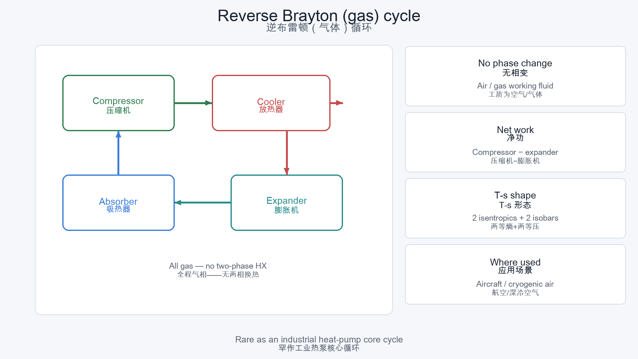
Reverse Brayton (Bell-Coleman / air cycle) stays in the gas phase: compressor → heat rejector → expander → heat absorber. No condenser or evaporator two-phase.
Where it appears
Aircraft environmental control, some cryogenic / air-cycle coolers, specialty gas processes. Occasional R&D mentions next to Stirling for exotic HTHP paths—not the industrial HP default.
Why it is rare as an industrial HP core
Without latent heat, you need large mass flow and heat-exchanger area for the same capacity; specific work and volume grow fast. Phase-change VCC usually wins on hardware density.
Do not confuse with power Brayton
Gas turbines run the forward Brayton cycle (produce work). Reverse Brayton consumes work to move heat. Same family name, opposite purpose.
3 · Subcritical vapor compression — the industry workhorse
Most chillers and heat pumps you meet are subcritical vapor-compression cycles (VCC): evaporate → compress → condense → throttle. Pressures stay below the fluid’s critical pressure on the high side.
Four processes ↔ four hardware roles
1→2 compression (compressor) · 2→3 heat rejection (condenser / desuperheat + subcool) · 3→4 expansion (valve or orifice) · 4→1 heat absorption (evaporator). Homepage config (a) Basic VCHP.
What P–h highlights
Superheat at suction, subcooling before the valve, compressor departure from isentropic, and how much enthalpy the throttle “throws away.” Those gaps drive economizers and staging.
Heating vs cooling is a bookkeeping choice
The loop is the same. Contracts must say whether kW means evaporator or condenser—and at which water/air temperatures. See also Part 3 · Pricing.
When single-stage hits the wall
Large ΔT raises pressure ratio and discharge temperature. Oil, seals, and maps fail before “marketing COP” does—enter Chapter 4 upgrades.
4 · Upgrades — economizer, two-stage, cascade
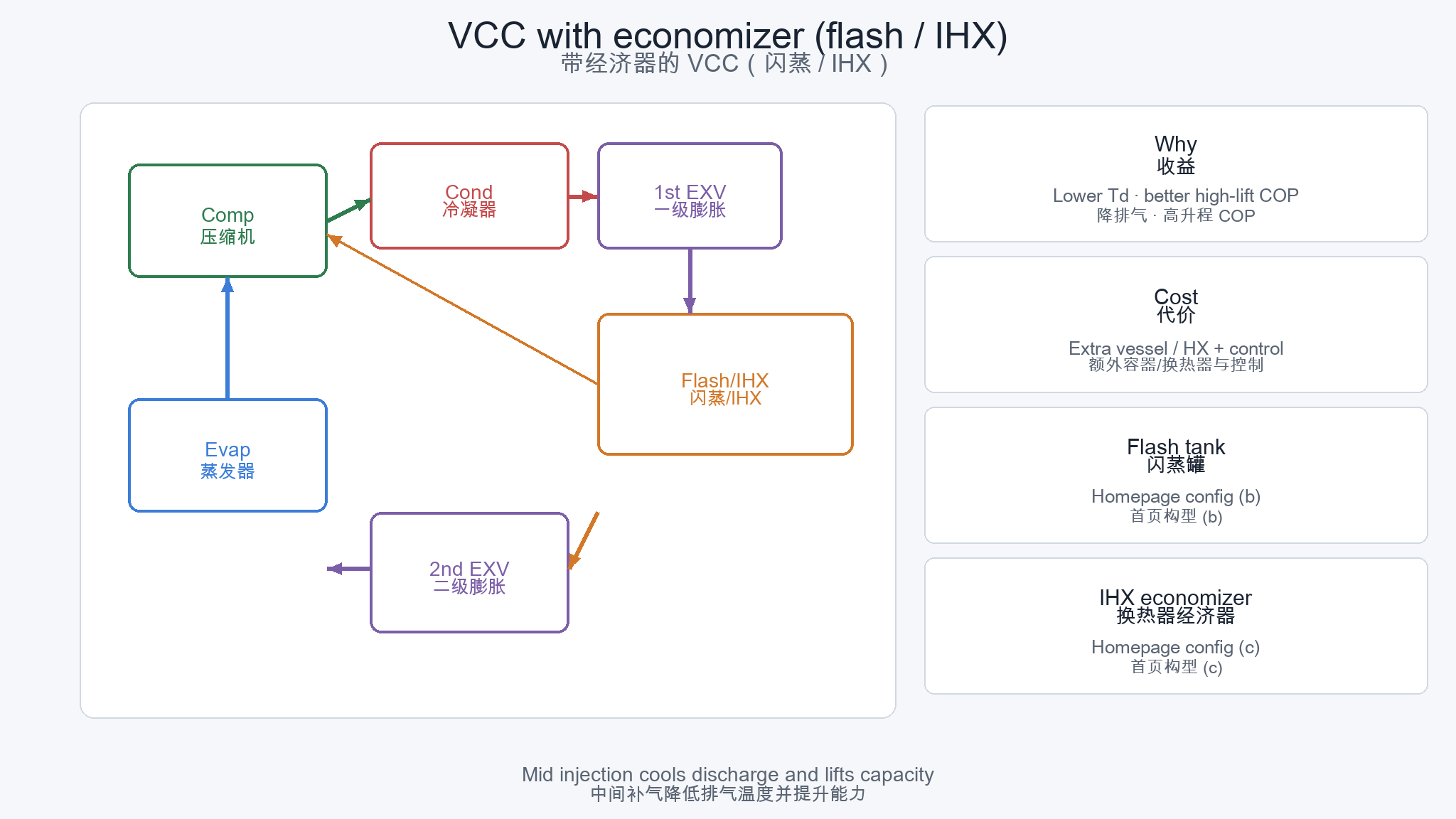
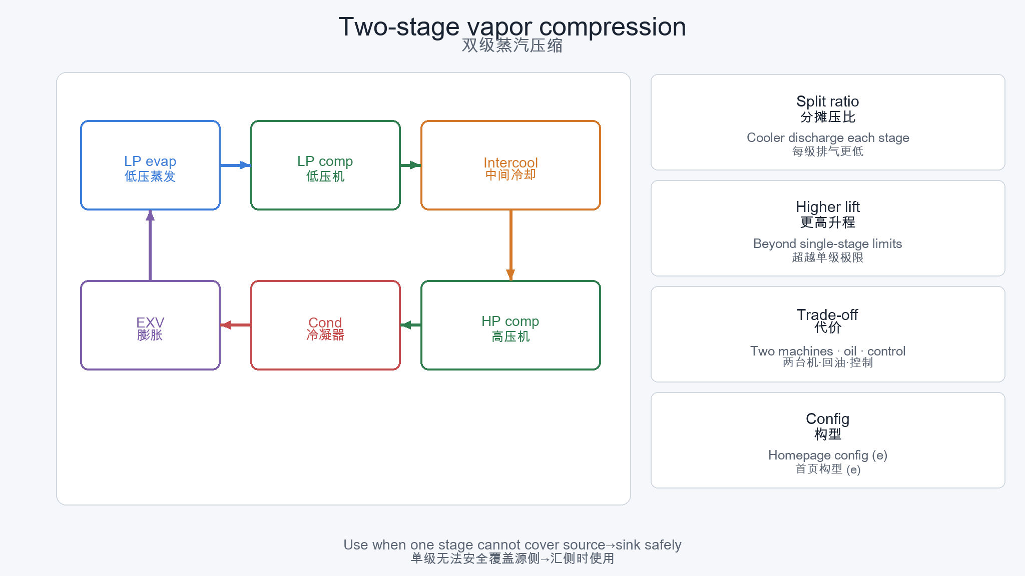
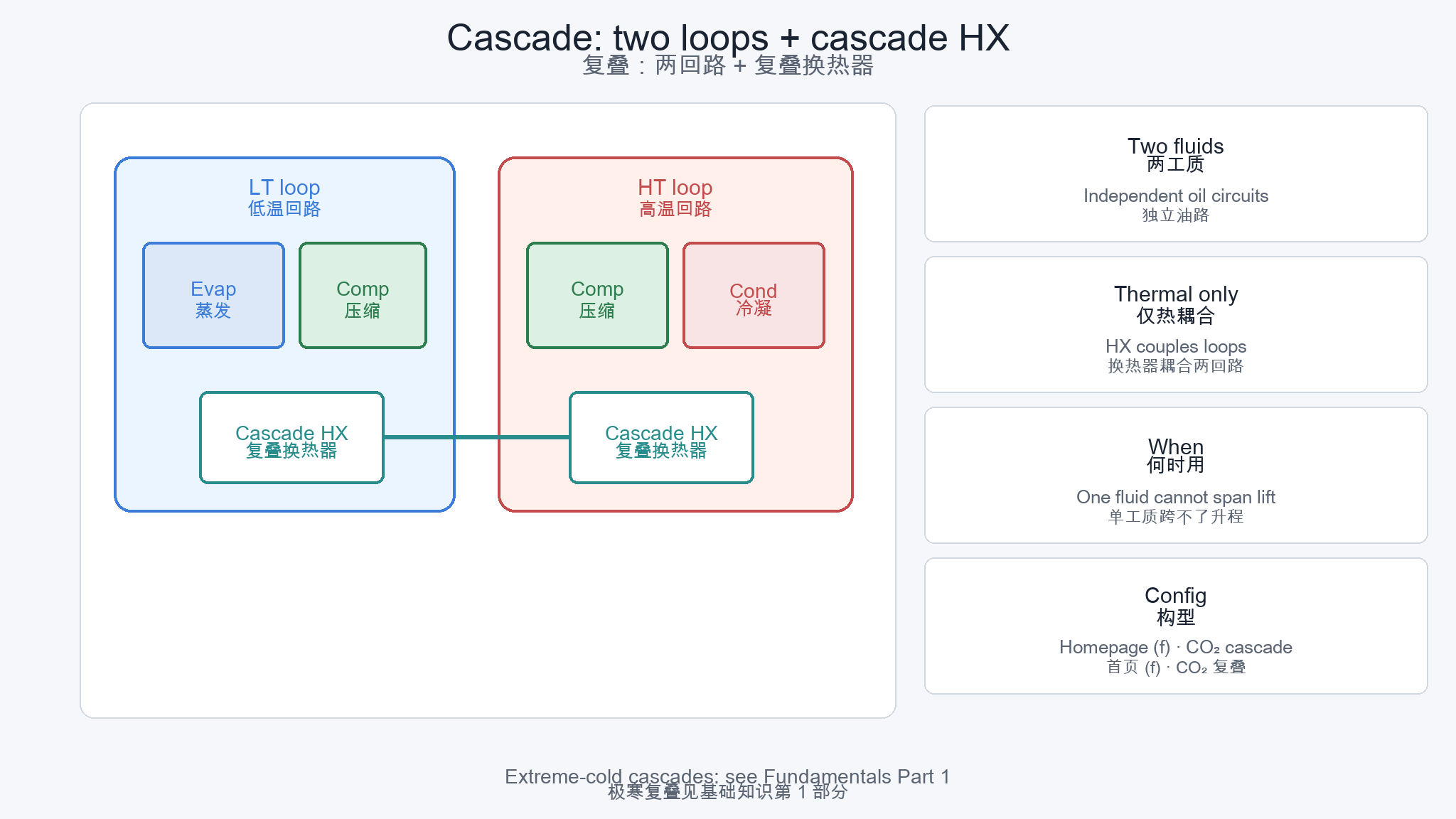
Same VCC physics, different staging. Names align with homepage HTHP configs (b)–(f) so toolbox calculators and this guide share one vocabulary.
Pick the upgrade for the pain
Discharge temperature / mild lift → economizer or injection. Large single-fluid lift → two-stage. Source and sink that no one fluid spans safely → cascade.
Ejector + IHX (config d)
Uses expansion work recovery via an ejector plus internal HX—another VCC upgrade family. See homepage config (d) when comparing proposals.
Cost is not only CAPEX
Every extra vessel and stage adds leak points, oil inventory, sensors, and commissioning hours. Reliability often decides before a spreadsheet COP delta.
5 · Transcritical CO₂ — gas cooler, not condenser
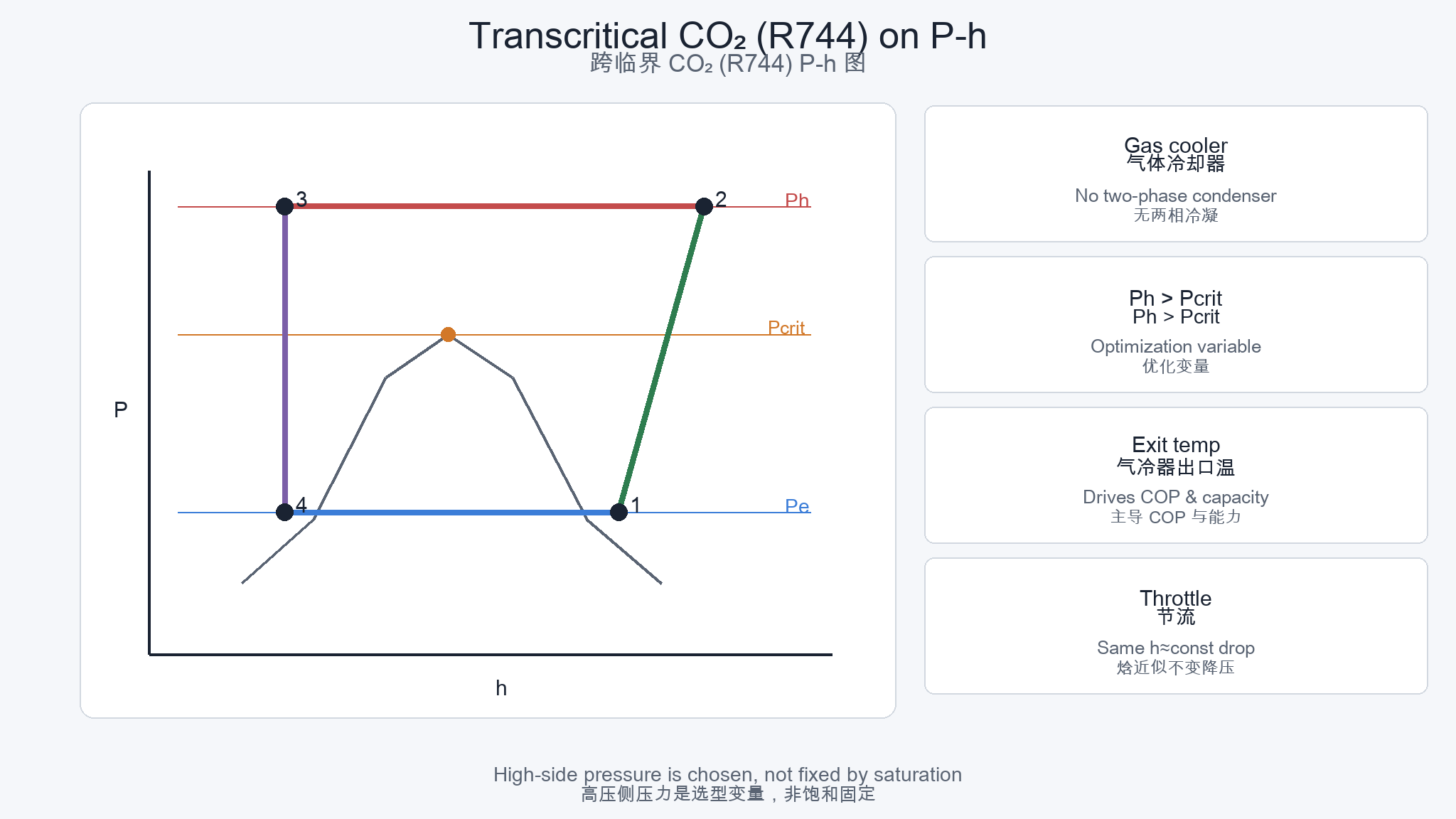
When high-side pressure sits above the critical pressure, there is no two-phase condensation. Heat rejection happens in a gas cooler; exit temperature—not a “condensing temperature”—sets much of the performance.
| Mode | High-side behavior | Pressure class (order) | Typical use |
|---|---|---|---|
| Subcritical CO₂ | Two-phase condenser possible | Still high vs many HFCs | Limited bands; often cascade LT stage |
| Transcritical CO₂ | Gas cooler · no condensation | Often ~80–120+ bar class | Hot water, commercial packs, some HP |
| CO₂ cascade (severe cold) | LT CO₂ + HT fluid loops | LT high; HT per fluid | Extreme-cold heating — Part 1 |
Language trap
Do not write “condensing temperature” into a transcritical duty sheet. Specify gas-cooler pressure and exit temperature (and sink inlet).
Control & maps
Optimal high pressure moves with gas-cooler exit temperature. OEM maps and controllers matter as much as heat-exchanger catalogues—see heat-exchanger guide (gas cooler vs condenser).
Fluid context
R744 selection, safety, and policy context: refrigerant guide. Standards pointer: GB/T 29707-class transcritical CO₂ heat-pump water heaters on Tools & Standards.
6 · Absorption — heat-driven “thermal compressor”
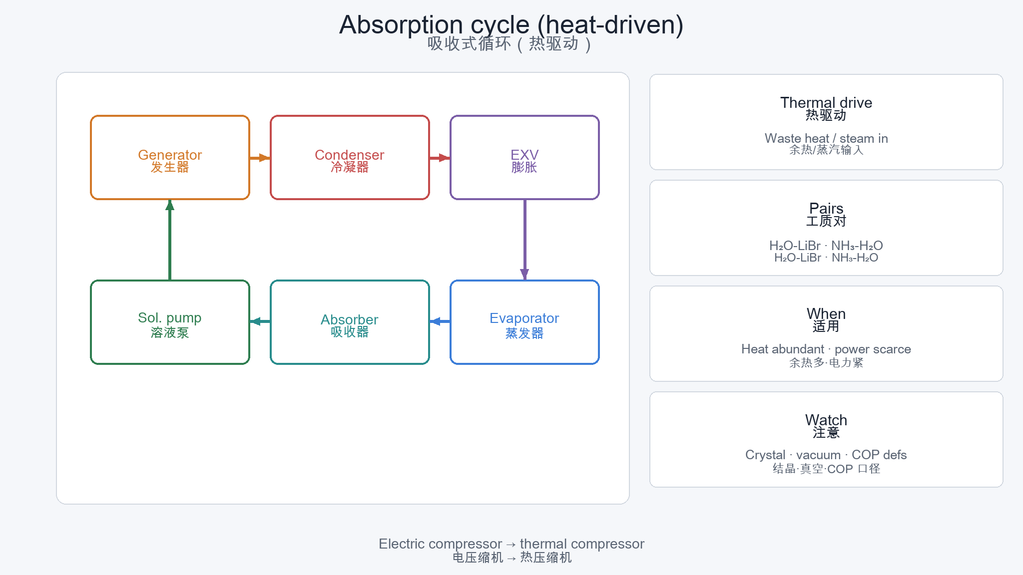
Absorption replaces the electric vapor compressor with a solution loop: generator (heat in) → condenser → evaporator → absorber → solution pump. Small pump work, large heat input.
When it wins
Abundant waste heat or steam, scarce or expensive power, or sites that prefer thermal integration over large electrical demand.
Boundaries
Crystallization (LiBr), vacuum integrity, corrosion, and maintenance culture. Not a drop-in substitute for a screw chiller without process and O&M review.
Hybrids
IIR-style roadmaps also cite absorption–compression hybrids—see Industrial HTHP column and standards notes.
7 · Open steam compression / MVR
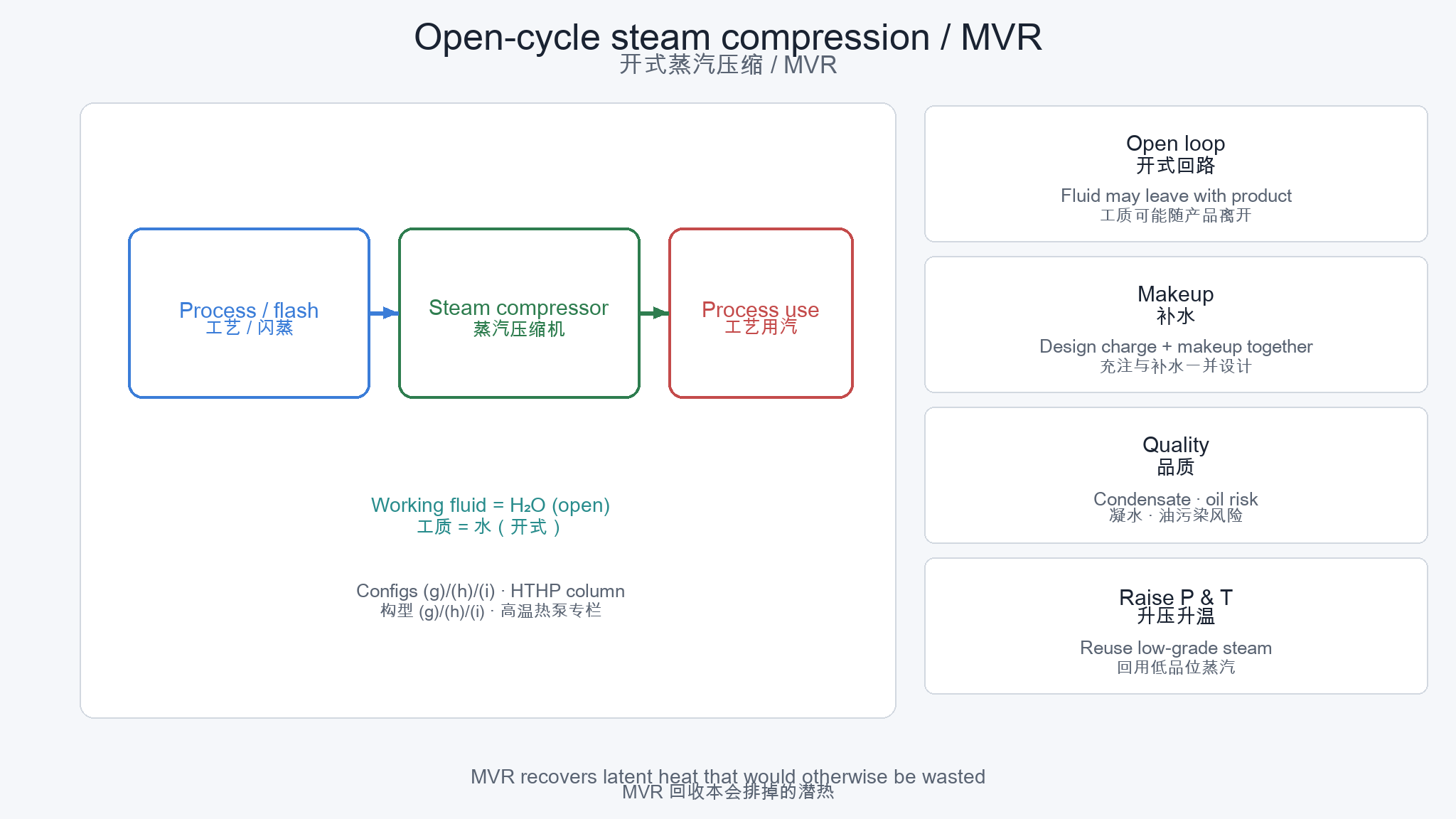
Here the working fluid is water vapor. A steam compressor (or MVR package) raises flash or process steam pressure for reuse—central to boiler-displacement narratives.
Not the same as a closed booster HP
MVR compresses process / flash steam in an open loop. A closed booster heat pump lifts reject heat with a separate refrigerant circuit—do not mix the names. See also Closed HTHP vs steam / MVR and Project Center recovery topologies.
Open-loop implications
Steam may leave with the product. Design makeup water, condensate recovery, and contamination (including oil) together with the compressor block.
Steam quality & turndown
Process cares about dryness, pressure stability, and part-load hours—not only a peak COP. Couple the heat-pump block with steam headers and controls.
Cascade + flash variants
Configs (h)/(i) combine cascade with flash or open steam—use when a single open loop cannot hit both source recovery and steam-grade sink.
8 · Selection map — ΔT & duty → cycle family
Start from temperature lift and sink type, then fluid and site constraints. The table is a first filter—not a substitute for OEM maps or process simulation.
| Lift / situation | Typical cycle | Fluid hints | On this site |
|---|---|---|---|
| Small ΔT | Single-stage VCC | Many HFC/HFO/HC; ammonia | Config (a) · compressor guide |
| Medium ΔT / high discharge risk | Economizer / IHX / injection | Per compressor map | Configs (b)–(d) |
| Large ΔT, one fluid preferred | Two-stage VCC | Industrial screws common | Config (e) |
| Very large span / severe cold | Cascade | Often CO₂ LT + HT fluid | Config (f) · Part 1 CO₂ |
| Hot water with R744 high side | Transcritical CO₂ | R744 gas cooler | Chapter 5 · refrigerants |
| Waste heat available, power scarce | Absorption (± hybrid) | H₂O–LiBr / NH₃–H₂O | Chapter 6 · HTHP column |
| Steam-grade sink | Open steam / MVR / flash cascade | R718 / steam | Configs (g)–(i) · HTHP |
Always lock source/sink temperatures, fluid safety class, and contract kW definition before comparing quotes. Gas-cycle Brayton remains a niche exception—not a default industrial HP path.
Next: pick hardware with the compressor, heat exchanger, and refrigerant guides—or jump to toolbox configs.
Quick FAQs
“Is reverse Carnot a product I can specify?”
No. It is a theoretical limit. Real machines are VCC, Brayton, absorption, etc., always below that COP ceiling for the same Tc/Th.
“Are refrigeration and heat-pump cycles different machines?”
Often the same loop with different useful-side bookkeeping and different Te/Tc. Industrial heat pumps usually run higher sink temperatures—so maps and staging change even when the cycle name stays “vapor compression.”
“Transcritical vs supercritical—same thing?”
In plant talk, “transcritical CO₂” usually means the high side is above critical pressure with a gas cooler. “Supercritical” is used more loosely in R&D; ask for Ph, gas-cooler exit T, and whether condensation exists.
“Why not always use reverse Brayton for simplicity—no phase change?”
No latent heat means larger flow and exchangers for the same kW. Industrial heat pumps almost always prefer phase-change VCC unless a specialty gas duty forces otherwise.
“Where do I go after choosing a cycle family?”
Fluid: refrigerant guide. Machines: compressor / HX / valves / vessels guides. Industrial steam narrative: HTHP column. Config calculators: homepage toolbox.
Schematics and COP formulas are engineering orientation only—not design calculations, OEM map substitutes, or safety-code advice. Confirm fluids, pressures, and envelopes with qualified design and type-test data.