Heat pump basics · Vessels
Vessel knowledge guide
Vessels manage oil, liquid slugs, charge storage, and intermediate flash—they are not “extra tanks” on the P&ID. An undersized accumulator or a mistuned oil return capillary fails as compressor damage, not as a quiet vessel fault. Pair with heat exchangers, valves, and compressors; OEM links under Tools & Standards.
1 · Role in the vapor-compression cycle
Compressors move vapor; vessels keep oil home, keep liquid off the suction flange, hold charge through mode changes, and stage flash where the cycle needs it. Vessel faults often present as “bad compressors.”
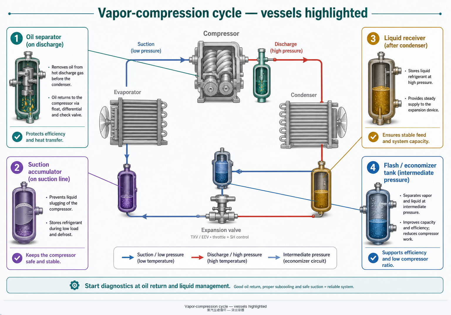
Oil management on discharge
Discharge mist carries oil into the circuit. Separators reclaim most of it and return it in a controlled stream so bearings stay wet while heat exchangers stay relatively clean. Details live with the compressor oil chapter.
Suction liquid protection
Accumulators (gas-liquid separators) buffer liquid slugs from overcharge, failed expansion control, flooded evaporators, or off-cycle migration—mechanical shock that compressors cannot survive repeatedly.
High-pressure storage & intermediate flash
Receivers store liquid after the condenser for pump-down and charge margin. Flash tanks / economizer vessels stage intermediate pressure—injection, ejector, or two-stage plants, including many high-lift duties.
2 · Vessel family overview
Use the family as a first filter: oil separator, suction accumulator, liquid receiver, flash tank, and (where used) oil reservoir each solve a different problem.
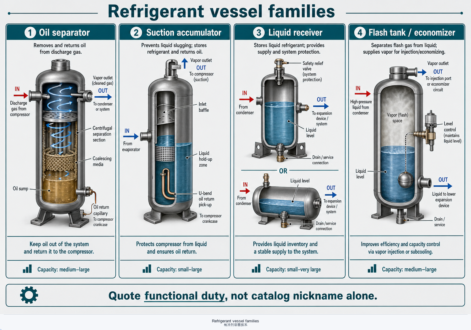
| Family | Primary job | Typical location | Typical failure mode | Heat-pump intuition |
|---|---|---|---|---|
| Oil separator | Strip discharge oil mist; return oil | Compressor discharge | Carry-over; clogged return; wrong ΔP | Inverter / long risers need proven return |
| Suction accumulator | Hold liquid; protect suction | Evaporator → compressor suction | Too small; oil trap; frost / SH loss | Reversible & flooded evaporators |
| Liquid receiver | Store liquid charge; enable pump-down | After condenser / before expansion | Undersized; level unknown; relief misuse | Mode change & seasonal charge margin |
| Flash tank / economizer | Intermediate flash; injection / staging | Between expansion stages / injection port | Level control; carry-over to suction | High-lift & economized maps |
| Oil reservoir (brief) | Hold & condition bulk oil inventory | Screw / large packs with oil loop | Wrong heater / level; foam & gas binding | Industrial packs more than comfort splits |
Some OEM packages combine separator + reservoir or receiver + dryer. Quote the functional duty, not the catalog nickname alone.
3 · Oil separators in depth
Separators reclaim discharge oil so the compressor stays lubricated and the evaporator stays efficient. Type, return capillary, and velocity all matter—see also the compressor oil chapter.
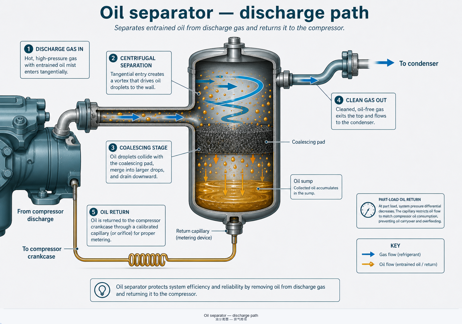
Centrifugal / coalescing / filter
Centrifugal units spin mist to the wall; coalescing pads grow droplets; filter elements trap fine aerosol. High-efficiency packs often stack stages. Confirm OEM rating at your refrigerant and oil, not a generic “99%.”
Oil return capillary
Return must meter oil home without dumping liquid refrigerant or starving the sump. Capillary diameter, length, and strainer cleanliness are reliability parts—clogged return looks like “sudden bearing failure.”
Velocity, ΔP, and mounting
Too-low velocity lets mist ride through; too-high ΔP wastes compressor lift. Keep orientation, heater (if specified), and vibration isolation per the vessel drawing.
Heat-pump & inverter notes
Low mass-flow at minimum inverter speed is the hard oil-return case. Prove separator + piping at the lowest continuous operating point, not only nameplate kW.
4 · Suction accumulators / gas-liquid separators
Accumulators buy time when liquid arrives at suction. They are not a license to ignore expansion control, charge, or evaporator design.
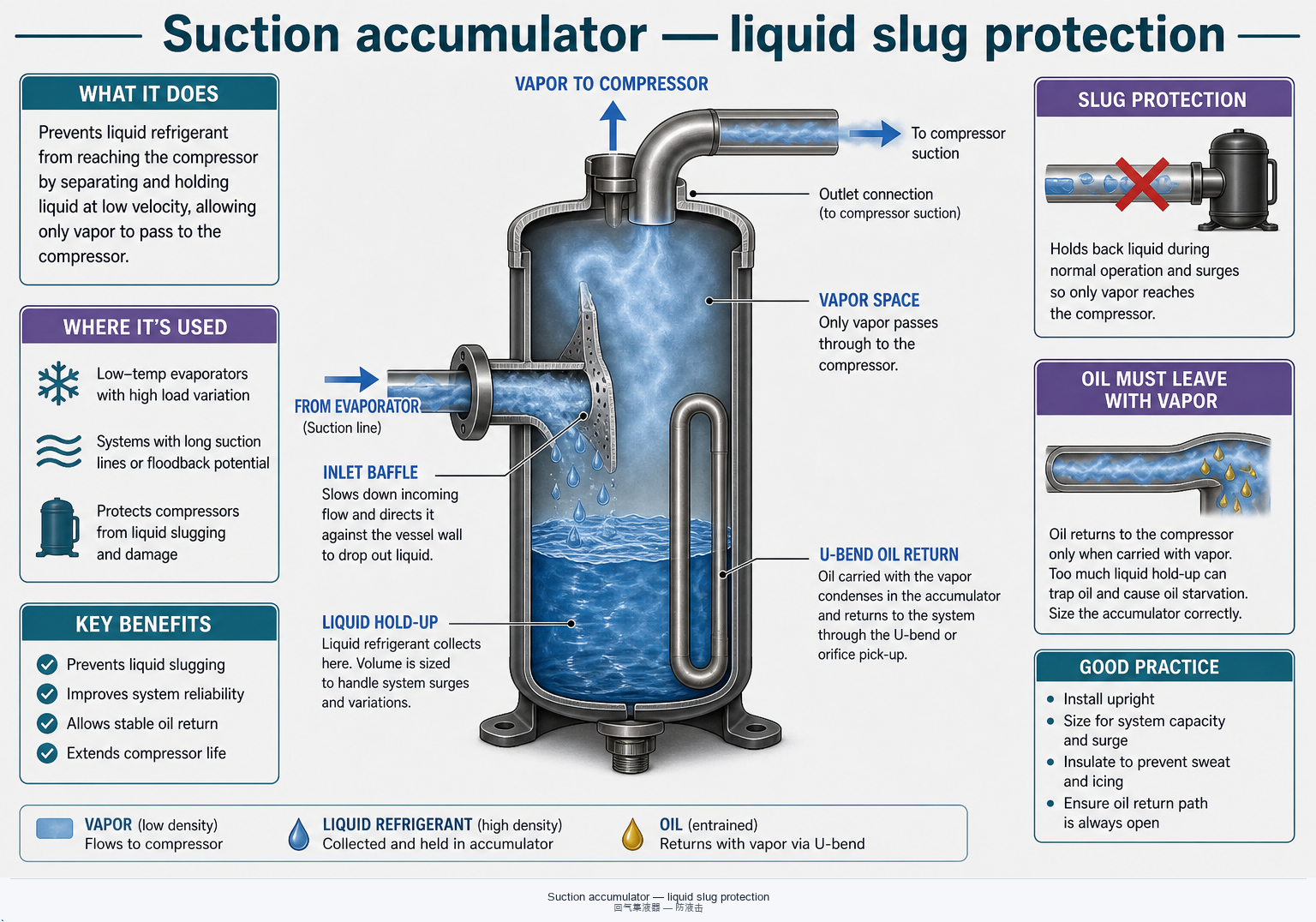
Liquid slug protection
Hold-up volume absorbs short liquid surges from mode change, defrost, or hunting expansion valves. Chronic flood-back needs root-cause fix—accumulators only delay mechanical damage.
U-bend oil return
A U-tube or pick-up meters a small liquid/oil film into the outlet vapor stream so oil returns with suction gas. Wrong orifice or missing screen strands oil in the shell.
Superheat boundary
Leaving SH at the compressor flange is the contract with the compressor map. A large cold accumulator can add heat gain or frost—insulate and place sensors where the control actually senses.
Sizing & reversible packs
Size for worst-case liquid dump, not average load. Reversible heat pumps and flooded evaporators need extra scrutiny on orientation and heater use in cold ambients.
5 · Liquid receivers
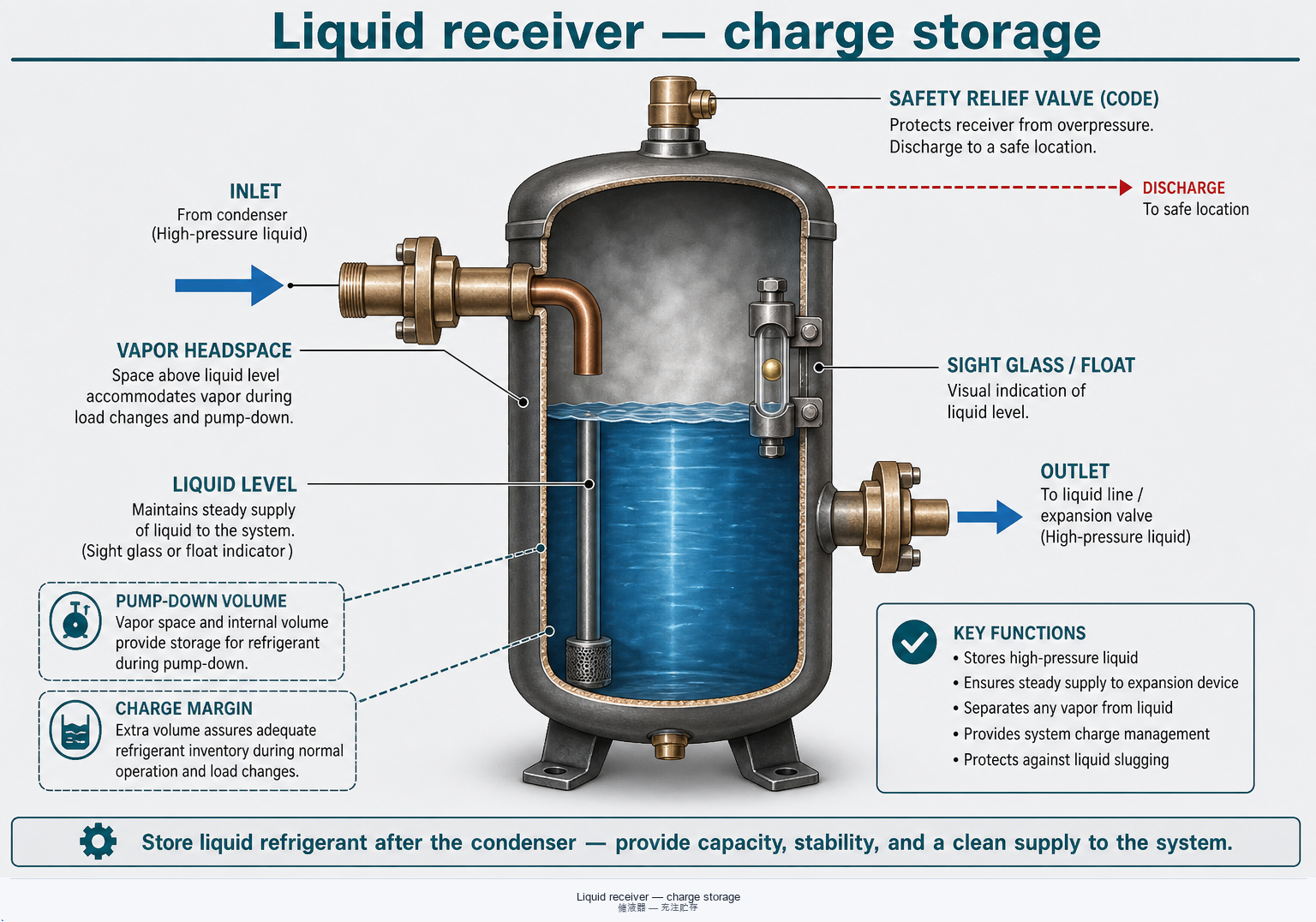
Receivers store high-pressure liquid after the condenser so charge can move with season, mode, and pump-down—without flooding the condenser or starving the expansion device.
After the condenser
Subcooled liquid enters; vapor headspace allows level change. Poor drainage or vapor binding raises condenser pressure and looks like “dirty HX.”
Pump-down & charge margin
Pump-down stores most charge in the receiver so evaporators can be isolated safely. Seasonal and heating/cooling mode swings need headroom—undersize forces chronic overcharge elsewhere.
Level indication
Sight glass, float, or electronic level turns “mystery charge” into a readable state. Blind receivers invite overcharge and liquid-line flash.
Safety relief
Relief protects the vessel and piping class. Set pressure, capacity, and discharge path are code decisions—not a modulating control opportunity. Pair with valve guide · relief thinking.
6 · Flash tanks / economizer vessels
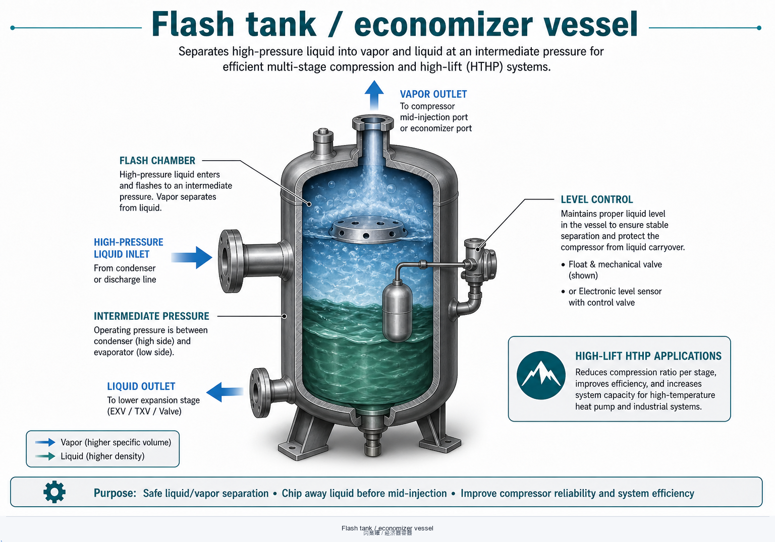
Flash vessels stage intermediate pressure: liquid flashes, vapor is separated, and streams feed injection ports, ejectors, or a second compression stage. Critical for many high-lift maps—see Industrial HTHP.
Intermediate cooling & economizing
Flash cooling lowers liquid enthalpy into the evaporator and can raise heating capacity at low source temperatures when maps include economizer / injection modes.
Ejector & two-stage plants
Ejector and compound systems use flash vessels as pressure nodes. Piping ΔP and nozzle/port matching belong to the OEM application note—not field improvisation.
HTHP high-lift duty
Large temperature lift multiplies pressure ratio stress. Staging and flash management are how packages stay inside envelopes—context in the HTHP column.
Controls & carry-over
Float valves, electronic level, or fixed orifices set the flash boundary. Hunting level or wet vapor to suction destroys the benefit and risks liquid at the wrong flange.
7 · Selection & layout checklist
Lock fluid, pressures, and protection duties before comparing catalog volumes or “standard kits.”
- Refrigerant & oil compatibility (miscibility, viscosity window, A2L / natural-fluid zoning).
- MAWP, volume, and relief aligned with piping class and code—not “closest stock shell.”
- Oil return path proven at minimum mass flow / inverter floor (separator capillary + accumulator pick-up).
- Liquid hold-up vs charge strategy: accumulator and receiver volumes match pump-down and mode swing—not guesswork.
- Layout: orientation, heaters, insulation, vibration, and service access per vessel drawing.
- Match the plant: same duty as compressor, HX, and valve maps; confirm economizer / flash with OEM software.
Need OEM catalogs and selection portals? Use Tools & Standards · links.
8 · Quick FAQs
“Do I always need both an oil separator and a suction accumulator?”
Not always—OEM packages decide by compressor type, piping length, and evaporator style. Separators address discharge oil mist; accumulators address suction liquid. Skipping either without analysis is a reliability bet.
“Why does oil still starve with a ‘high-efficiency’ separator?”
Return capillary clogging, wrong part-load velocity, long risers, or oil hold-up in evaporators/headers. Trace the full return path—see compressor oil.
“Is a larger receiver always safer?”
Larger volume helps charge margin and pump-down, but excess charge and poor level visibility create other risks. Size to the duty and keep relief correct.
“Where next on this site?”
Heat exchangers · Valves · Electrical & controls · Fundamentals · Industrial HTHP.
OEM application limits, vessel design codes, and relief editions vary by product and jurisdiction. This page is engineering orientation—not a substitute for manufacturer manuals, PED/ASME practice, or licensed design.