Heat pump basics · Compressors
Compressor knowledge guide
The compressor is the heart of the vapor-compression machine—it sets pressure ratio, mass flow, and much of the reliability risk. This illustrated guide covers types, construction, how to read performance maps, oil management, and heat-pump / high-lift specifics. For the Chinese trade label 匹 and quote traps, see the fundamentals chapter; for OEM selection tools, use Tools & Standards.
1 · Role in the vapor-compression cycle
A boiler makes heat. A heat pump moves heat—and the compressor is what creates the pressure difference that makes that move possible. For the full cycle family map (Carnot → VCC upgrades → transcritical / absorption / steam), see the cycle guide.
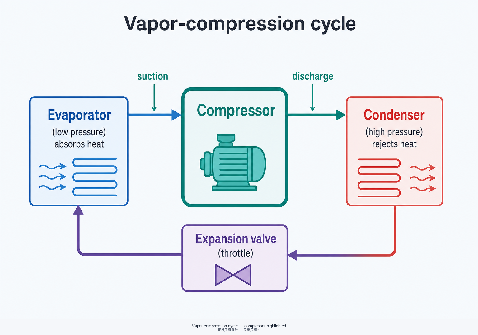
Pressure lift + mass flow
Suction gas from the evaporator is compressed to discharge pressure. Capacity scales with displacement × suction density × volumetric efficiency. Change evaporation or condensation temperature and both kW and power move—there is no “size” detached from duty.
Heat pump vs pure refrigeration
Cooling duty values the evaporator; heating duty values the condenser (and often a higher sink temperature). The same frame can look “big” on a comfort cooling map and undersized on a high-lift heating map. Always state source and sink temperatures.
Where reliability risk concentrates
Liquid slugging, oil starvation, excessive discharge temperature, and wrong oil return design usually show up first at the compressor—even when the root cause is evaporator or piping design.
2 · Machine families
No single compressor type wins every band of capacity, lift, and refrigerant. Use the family as a first filter, then confirm with OEM maps.
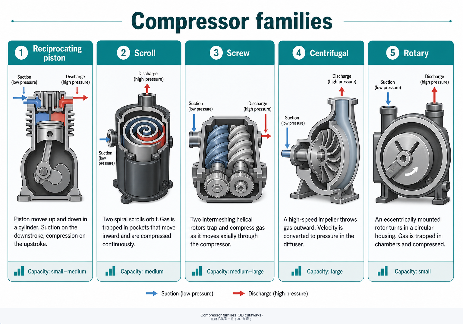
| Family | Typical capacity band | Lift / pressure ratio | Oil notes | Capacity control | Heat-pump intuition |
|---|---|---|---|---|---|
| Reciprocating | Small–medium (kW to low hundreds) | Wide; multi-stage for deep cold | Crankcase oil; mist carry-over | Unloaders, cylinder cut-out, inverter | Common in commercial packs; robust at moderate lift |
| Scroll | Small–medium (residential to light commercial) | Good for comfort HP; check high-lift maps | Often POE with HFC/HFO; return critical | Inverter / digital scroll | Dominant in air-to-water comfort; injection variants for cold climate |
| Screw | Medium–large | Strong for industrial HP & chillers | Oil injection / separator loop central | Slide valve, Vi, inverter | Workhorse for many HTHP and industrial plants |
| Centrifugal | Large (MW-class possible) | Best near design tip speed; surge limits | Oil-free maglev options exist | IGV, VFD, inlet guide | Large chillers; selected HTHP / steam HP concepts |
| Rotary (rolling piston) | Small | Comfort & specialty packs | Compact oil sump; orientation matters | Inverter common | Room AC / small HP; less common as industrial core |
Bands are engineering shorthand. Final choice always follows refrigerant, evaporating/condensing (or air/water) temperatures, and OEM operating envelopes.
3 · Hermetic, semi-hermetic, and open-drive
How the motor and shell are packaged changes serviceability, leak paths, and which sites will accept the machine.
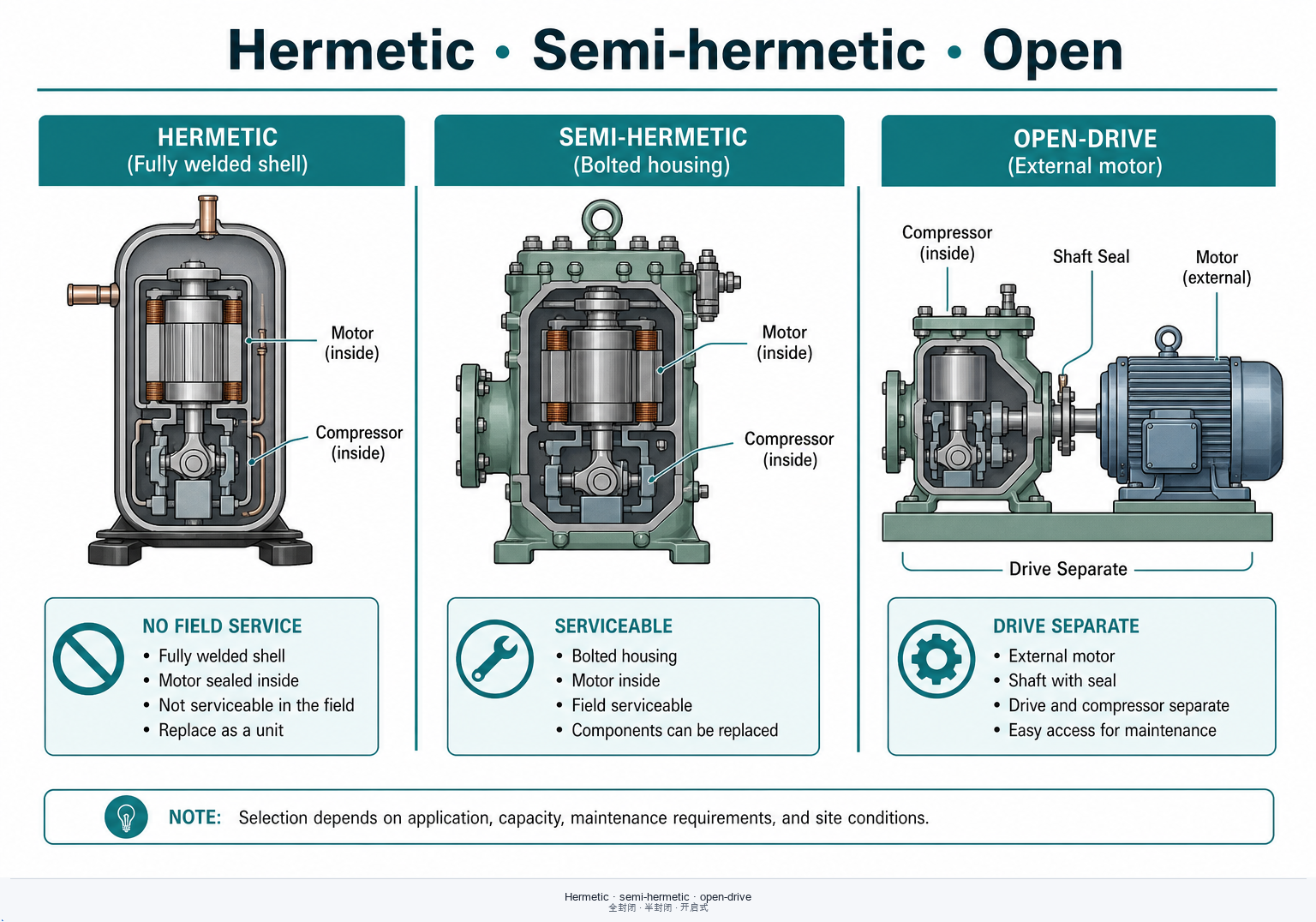
Hermetic
Motor and pump in a welded shell. Compact and leak-tight for mass production (scroll / rotary). Limited field rebuild—failure often means replace. Motor cooled by suction gas or dedicated cooling path.
Semi-hermetic
Bolted housing; motor still refrigerant-cooled inside. Dominant for many commercial and industrial piston/screw lines because bearings, valves, and rotors can be serviced. Still a pressure vessel—bolt torque and gasket practice matter.
Open-drive
External motor (electric or engine) with a shaft seal. Flexible drives and motor swaps; seal leakage and alignment become O&M items. Common historically on large ammonia plants; less common on small fluorocarbon packs.
Safety & A2L / natural fluids
Flammable or toxic refrigerants add charge limits, ventilation, and electrical zoning—not just “pick a frame.” Confirm OEM qualification for the fluid (e.g. R290, R717, R744) and site codes before freezing the BOM.
4 · Performance maps and key parameters
Catalog “horsepower” or a single kW number is not a map. Capacity and power are surfaces over evaporating and condensing temperature—and sometimes superheat, subcooling, and speed.
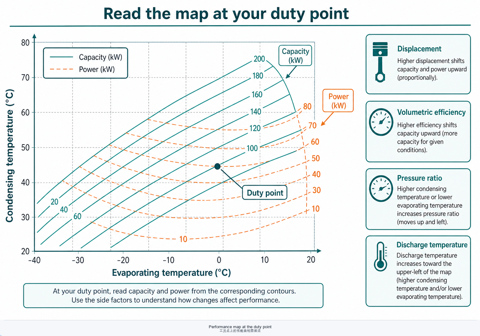
Displacement & volumetric efficiency
Geometric displacement sets the scale; volumetric efficiency falls as pressure ratio rises and with valve/port losses. Two machines with the same “cc” can deliver different mass flow at the same suction condition.
Pressure ratio & discharge temperature
High lift pushes discharge temperature and oil stress. Injection (liquid or vapor), economizers, or staged compression exist because a single stage hits thermal or mechanical limits.
Superheat at the suction flange
Too little risk liquid; too much cuts mass flow and raises discharge temperature. Map points assume a defined superheat—align your control strategy with the OEM assumption.
One-sentence memory
Same frame, different Te/Tc → different kW. If the quote omits source/sink temperatures, you are not yet comparing machines.
5 · Lubrication, oil return, and reliability
Oil must lubricate bearings and rotors, then come home. Most “compressor failures” that survive root-cause analysis are system oil or liquid-management problems. For oil chemistry and family selection, see the lubricant guide.
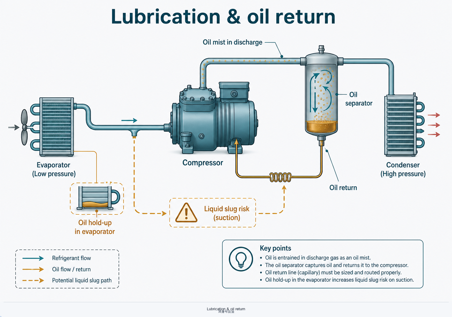
Oil leave, oil return
Discharge mist carries oil into the circuit. Separators reclaim most of it; the rest must return from evaporators and headers. Low mass-flow, long risers, or wrong traps strand oil—bearings starve while heat exchangers foul.
Liquid slugging
Liquid at the suction flange is mechanical shock. Causes include overcharge, failed expansion control, flooded evaporators, or migration after long off-cycles. A field case of multi-machine seizure traced to evaporator design is documented in Screw seizure & liquid-slug tolerance.
High-temperature oil stress
HTHP duty can carbonize oil or exceed viscosity windows. That is why oil-free / maglev paths appear in R&D roadmaps—see Industrial HTHP · advanced compressors.
6 · Heat-pump and high-lift specifics
Heating at large temperature lift is not “a chiller run backwards.” Pressure ratio, injection strategy, and part-load hours dominate life-cycle cost.
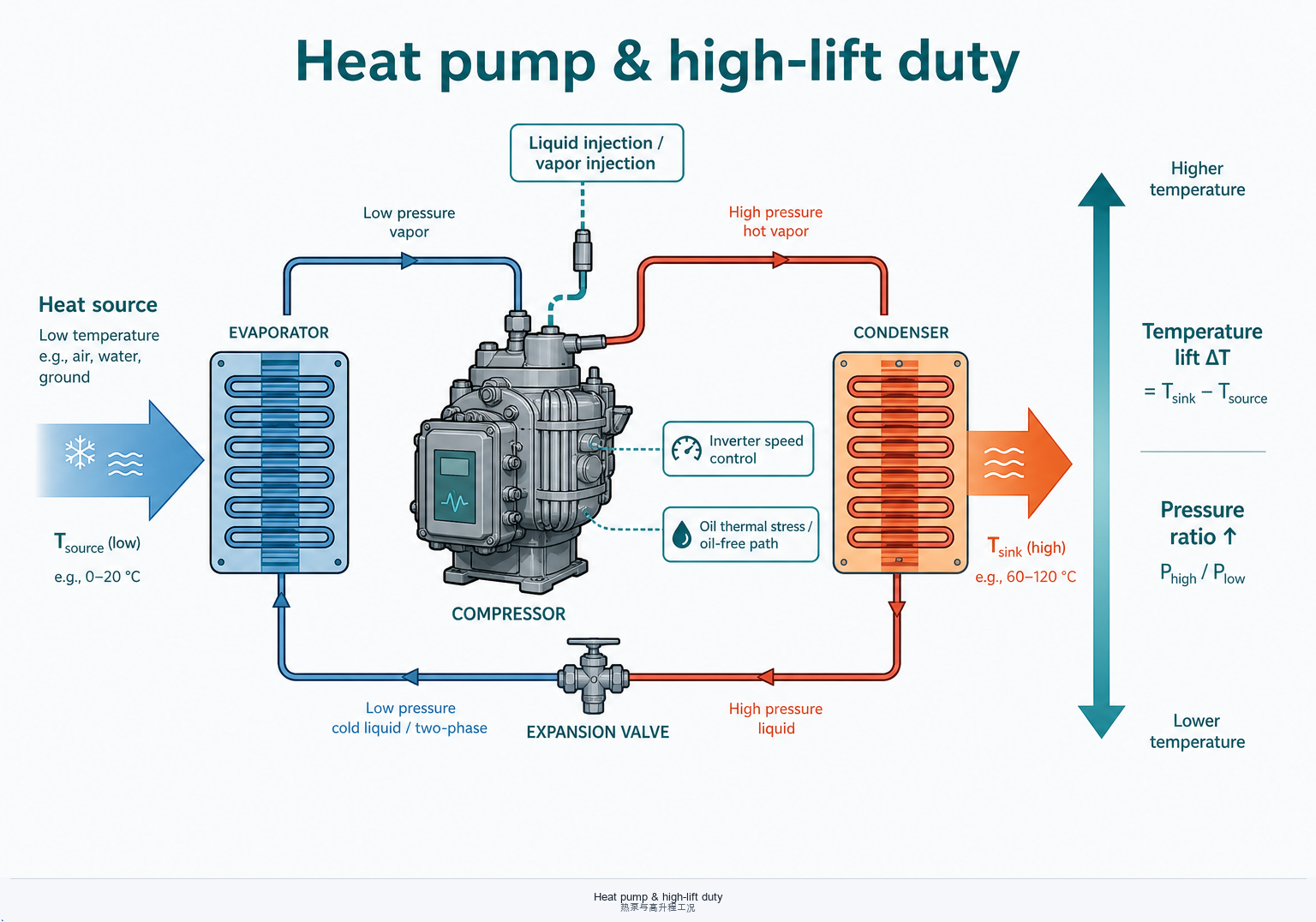
Injection & economizer
Liquid or vapor injection cools discharge gas and can raise heating capacity at low source temperatures. Confirm the map includes your injection mode—not only the dry-suction envelope.
Inverter & part load
Annual energy often hinges on part-load COP and minimum speed oil return, not peak nameplate. Ask for maps at several speeds and the lowest continuous operating point.
Natural fluids: CO₂, ammonia, hydrocarbons
R744 means high pressure and often transcritical gas coolers; R717 means toxicity/zoning and oil miscibility choices; R290 means charge and ignition source control. Pair fluid knowledge from the refrigerant guide with compressor OEM qualification.
Toward oil-free / maglev
For frequent start-stop and high-duty steam service, oil management can be the bottleneck—not heat-exchanger catalogues. Context: HTHP R&D themes.
7 · Selection checklist
Before comparing price or “匹”, lock the engineering boundary. Then open OEM software with the same inputs.
- Refrigerant (and blend glide / safety class) locked with the system designer.
- Source & sink temperatures at design and at a realistic part-load / cold-climate point.
- Heating vs cooling capacity definition—and whether condenser or evaporator kW is the contract metric.
- Supply boundary: compressor only vs package; oil separator, inverter, and auxiliaries in or out of the quoted kW/COP.
- Contract language: kW @ stated conditions—not 匹 alone. See Compressor “匹” chapter.
- Cross-check OEM tools on the Tools & Standards · OEM links page (Bitzer, Dorin, Bock, etc.).
Still comparing quotes with mismatched rulers? Return to Part 3 · Pricing & standards in the fundamentals series.
8 · Quick FAQs
“Can I size by motor kW alone?”
No. Motor power is not delivered heating or cooling kW. Use capacity tables at your Te/Tc (or air/water temperatures) and confirm absorbed power separately for electrical design.
“Why does the same screw look fine on paper but seize in the field?”
Often liquid management or oil return—not a random manufacturing defect. Trace evaporator design, traps, and off-cycle migration. Case study: screw seizure insight.
“Is inverter always better for heat pumps?”
Often yes for part-load comfort and soft start—but only if oil return and minimum speed are proven for your piping. A poorly applied inverter can starve oil at low mass flow.
“Where do I go next on this site?”
匹 / rating traps · Lubricants · Refrigerants · HTHP compressors · OEM selection links.
OEM envelopes, oil specs, and standard editions vary by product and year. This page is engineering orientation for buyers and integrators—not a substitute for type-test reports, signed data sheets, or safety-code compliance.