Heat pump basics · Piping systems
Piping systems knowledge guide
Piping is not “tube that connects components”—it is a flow, oil-return, and vibration path that decides whether the pack stays inside its map. Undersize a suction riser and you starve oil; oversize a liquid line and you lose velocity for return. Pair with lubricants, compressor oil return, vessels, and enclosure; this page focuses on refrigerant piping geometry and protection.
1 · Role in the heat-pump system
Every metre of pipe spends pressure, carries oil mist, and transmits vibration. Treat piping as part of the thermodynamic and reliability story—not as afterthought routing.
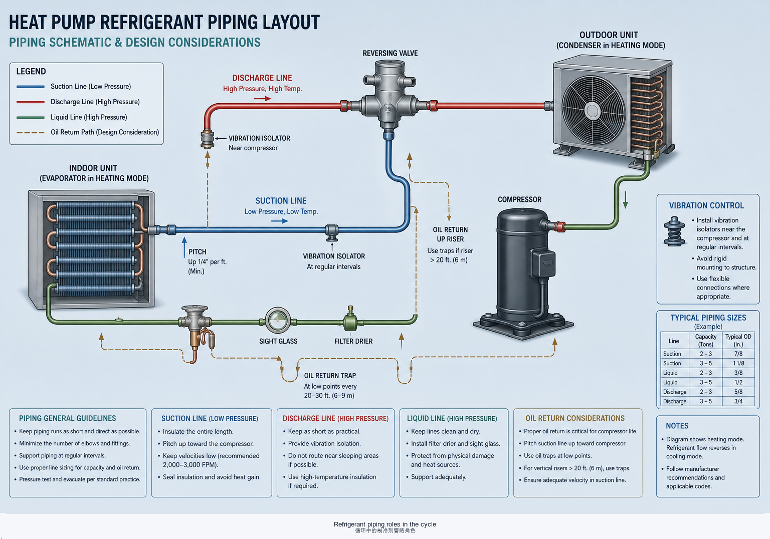
Pressure drop
Suction drop cuts capacity and raises compressor work; discharge drop lifts head and discharge temperature. Liquid-line drop risks flash gas ahead of the expansion device. Budget ΔP on the selection sheet, not after the isometric is frozen.
Oil return
Oil travels as mist and film. Velocity, risers, traps, and separators decide whether it comes home—especially at inverter minimum speed. See lubricants and compressor oil chapter; vessels reclaim what piping cannot.
Vibration & stress
Compressor discharge is a mechanical driver. Rigid short stubs without isolation or loops crack fittings and fatigue braze joints. Piping that “looks neat” can still be a fatigue machine.
2 · Diameter, slope, risers, and support spacing
Catalog tube sizes are a start. Velocity for oil entrainment, slope for drainage, and riser design for lift decide part-load survival.
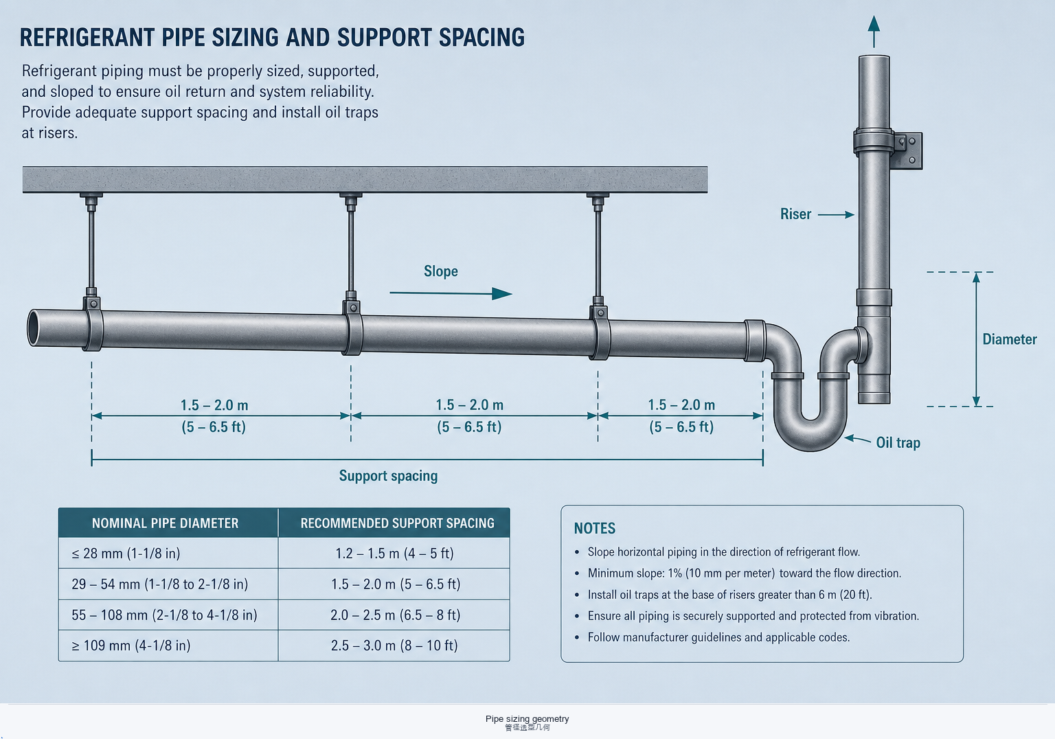
Diameter & velocity
Size suction for acceptable ΔP and oil-carrying velocity at minimum continuous mass flow. Discharge and liquid lines need their own velocity windows—do not copy suction diameter by habit.
Slope & drainage
Horizontal suction and discharge runs usually slope toward the compressor or toward drains/traps so oil and condensate do not pool in dead legs. Wrong slope creates silent oil traps.
Risers & traps
Vertical lifts need traps and, at wide turndown, double risers or equivalent OEM schemes so oil is lifted without flooding the compressor on start. Pair with oil separators when carry-over is high.
Support spacing
Unsupported spans sag, change slope, and amplify vibration. Spacing depends on tube diameter, insulation mass, and filled weight—treat manufacturer tables as starting points, then check at bends and valve clusters.
3 · Support types, vibration isolation, and thermal expansion
Clamps hold geometry; isolators break vibration paths; expansion loops absorb growth. Missing any one turns a tidy rack into a leak factory after a few seasons.
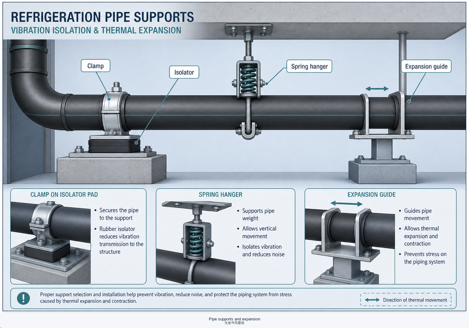
Support types
Clevis hangers, saddle clamps, and channel mounts each suit different loads. Insulated lines need cradles that do not crush vapor barrier; hot discharge needs materials that tolerate temperature.
Vibration isolation
Flexible connectors, spring hangers, and rubber mounts interrupt structure-borne noise. Place isolation near the source; downstream rigid runs should not re-couple into the cabinet or building steel.
Thermal expansion
Copper and steel grow with temperature. Long hot gas lines need loops, offsets, or expansion joints so anchors do not tear joints. Cold suction lines shrink—account for both extremes in the same layout.
4 · Corrosion protection and insulation
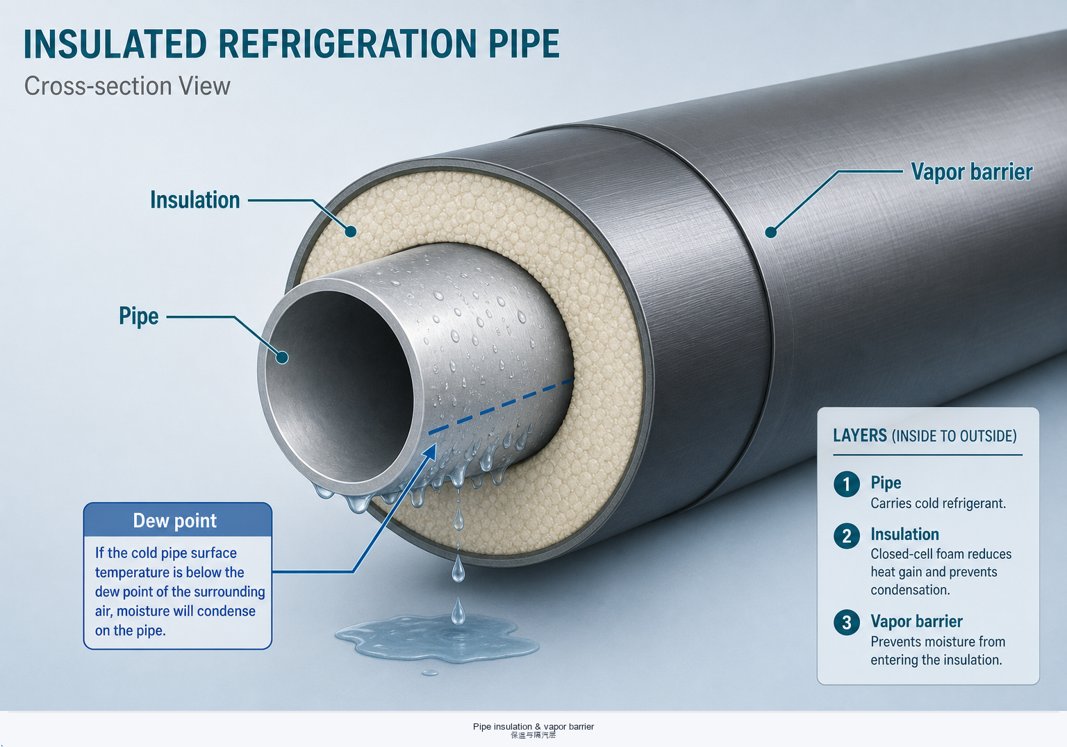
Metal and insulation fail as a pair: corrosion under insulation (CUI), wet vapor barriers, and dew-point sweat destroy reliability as surely as wrong diameter.
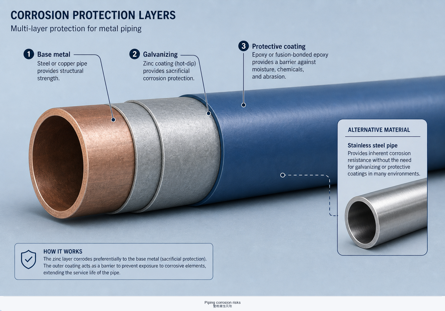
Corrosion & materials
Match tube and fitting alloys to refrigerant, oil, and ambient (coastal, industrial, plant-room condensate). Protect carbon steel; isolate copper–steel couples; keep water off joints.
Insulation materials
Closed-cell elastomeric, PIR/PUR, and mineral wool each fit temperature and fire-code niches. Hot discharge and cold suction rarely share one product without checking temperature limits.
Vapor barrier & dew point
On suction and cold liquid lines, a continuous vapor barrier stops moist air reaching the cold metal. Seams, valve bodies, and hanger penetrations are the usual failure points—tape and mastic are part of the design, not cosmetics.
One-sentence memory
Wet insulation is a corrosion machine—fix dew point and barrier integrity before arguing about an extra millimetre of foam.
5 · Selection & layout checklist
Freeze fluid, capacity, and compressor map first; piping is the network that must keep oil and ΔP honest across the whole turndown range.
- Mass-flow window locked (design + inverter minimum)—size suction for oil return at the low end.
- ΔP budget for suction, discharge, and liquid—flash risk ahead of the expansion device checked.
- Risers, traps, slope per OEM application note; separators where carry-over demands—see vessels.
- Supports & isolation: spacing, vibration breaks, expansion loops; no rub points into the enclosure.
- Corrosion & insulation: materials, coatings, vapor barrier continuity, dew-point thickness.
- Serviceability: valves, driers, and joints accessible; oil story aligned with lubricants and compressor oil.
Need oil chemistry or separator geometry next? Continue at Lubricants or Oil separators.
6 · Quick FAQs
“Can I upsize suction pipe to cut pressure drop?”
Only if oil-carrying velocity still holds at minimum continuous mass flow. Oversized suction is a classic oil-starvation path on inverter packs—see compressor oil chapter.
“Why does the discharge line crack near the compressor?”
Usually rigid mounting plus vibration and thermal growth. Add isolation, a flexible section or loop, and proper supports—do not just “reinforce the braze.”
“Is thicker insulation always better on suction?”
Thickness must beat dew point and keep the vapor barrier intact. Thick foam with open seams still sweats and corrodes.
“Where next on this site?”
Lubricants · Compressor oil · Vessels · Enclosure.
Piping codes, OEM application manuals, and insulation standards vary by product, fluid, and jurisdiction. This page is engineering orientation—not a substitute for signed isometrics, stress analysis, or type-test layout rules.