Heat pump basics · Electrical & controls
Electrical & controls knowledge guide
The electrical layer turns thermodynamics into drive, protection, capacity control, and safe mode changes. A VFD is not “just soft start”—it reshapes part-load COP and harmonic budgets. Controllers and IoT add visibility; they do not repeal sensor placement or lockout logic. Pair with compressors, valves, and vessels; OEM links under Tools & Standards.
1 · Roles of the electrical layer
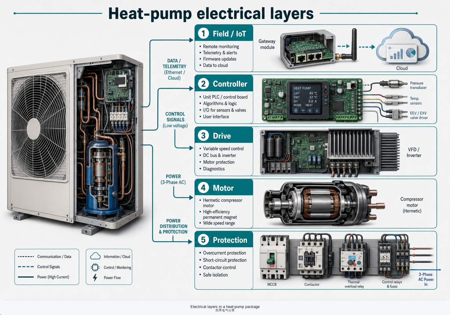
Mechanical parts move heat; electrics decide when they may run, how hard they run, and what happens when sensors disagree. Treat drive, protection, capacity, and interlocks as one system—not four separate BOMs.
Drive
Mains, contactors or VFDs, and the motor convert electrical power into shaft work (or into a hermetic rotor). Wrong voltage, phase loss, or undersized cable shows up as trips long before COP collapses on paper.
Protection & interlocks
Breakers, thermal relays, HP/LP switches, flow and frost cut-outs form hard stops. Interlocks enforce sequence—do not bypass a lockout to “keep heating” without knowing what it was guarding.
Capacity control & monitoring
Unloaders, inverter speed, and staged auxiliaries hold the plant on the map. Monitoring (P/T, current, status bits) feeds the controller and any remote layer—garbage in means clever algorithms still fail.
2 · Motors
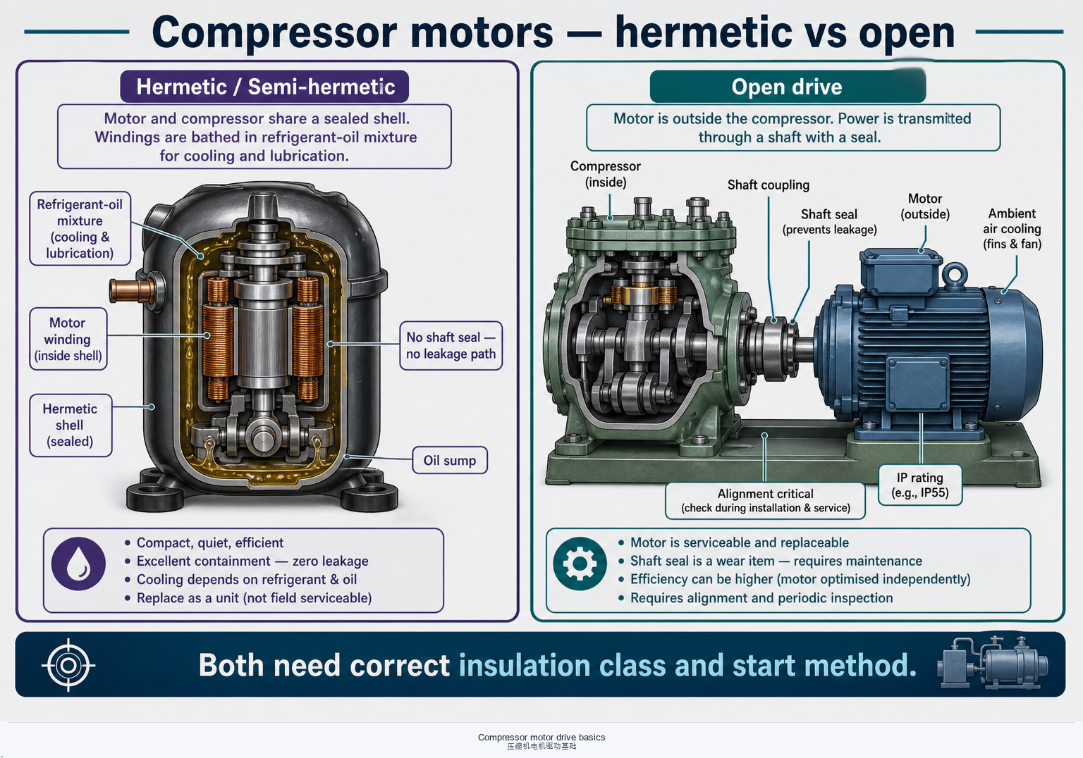
Hermetic and open motors share insulation and inrush physics, but live in different environments. Motor choice is inseparable from the compressor envelope.
Hermetic vs open
Hermetic / semi-hermetic rotors run in refrigerant–oil mixture—compatibility and winding temperature limits belong to the OEM. Open motors couple through a shaft seal; misalignment and seal leak are mechanical–electrical joint failures. See compressor construction.
Insulation class & temperature rise
Class F/H ratings are not a free pass for poor cooling or VFD heating. Discharge temperature, liquid flood-back, and PWM carrier losses all eat insulation life.
Inrush & start method
DOL inrush can be 5–8× FLC; soft starters and VFDs cut peak demand and mechanical shock. Confirm utility limits and whether the compressor allows soft start without oil-pressure race conditions.
IP rating & environment
Outdoor packs, dusty plant rooms, and wash-down zones need matching enclosure IP and cable glands. Condensation inside a “sealed” terminal box is a classic intermittent ground fault.
3 · VFDs / inverters
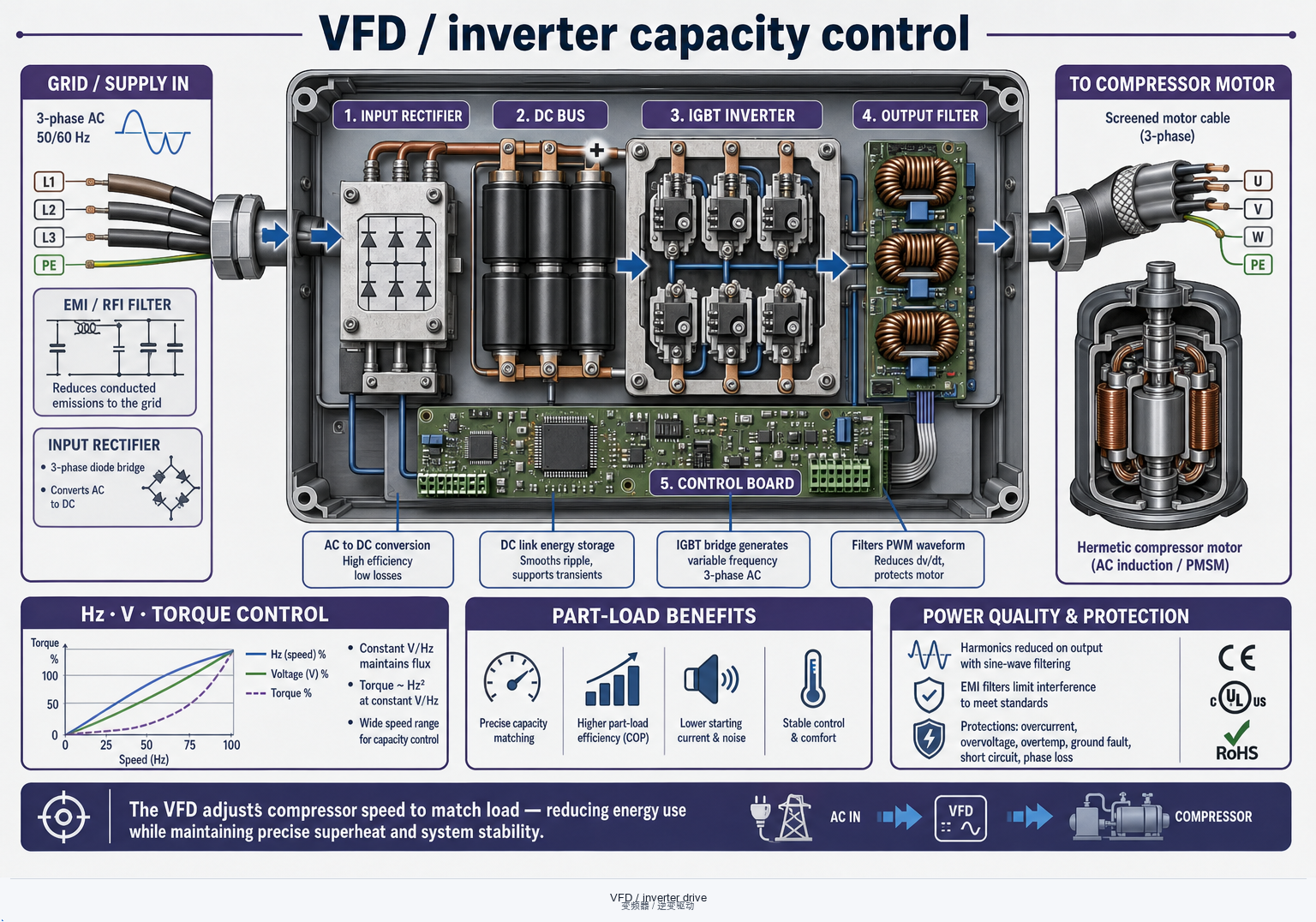
Inverters unlock part-load COP and soft start—but they add carrier noise, harmonics, and minimum-speed oil-return constraints that mechanical unloaders never had.
Carrier, cable & EMI
PWM carrier frequency and motor-cable length drive dV/dt stress and radiated noise. Use screened cable, proper earthing, and OEM filter kits when the panel sits far from the compressor.
Harmonics & supply quality
Six-pulse front ends inject harmonics; weak grids and generator supplies may need reactors or active filters. Undersized transformers overheat even when “amps look fine.”
Part-load COP vs mechanical unload
Speed turndown often beats slide valves or hot-gas bypass on seasonal efficiency—provided evaporator mass flow and oil return stay inside the map. A fast VFD on a starved oil circuit is not an upgrade.
Integration checklist
Match motor insulation for inverter duty, set torque/current limits, and wire fault relays into the unit controller. Never treat the VFD keypad as a substitute for safety interlocks.
4 · Unit controllers / PLC
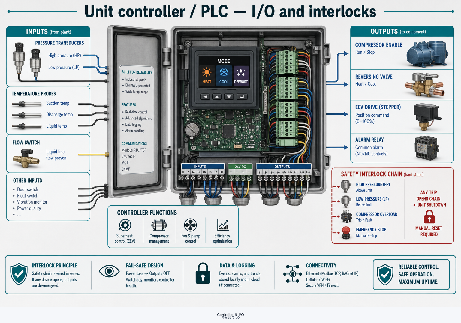
The controller is the plant’s operating brain: it reads sensors, enforces safety, and switches modes. Firmware maps matter as much as the hardware BOM.
Sensors & signal integrity
Pressure transducers, NTC/PT1000 probes, and flow switches must see the state you intend. Wrong placement or shared grounds create hunting that looks like a “bad EEV” or “weak compressor.”
Safety interlocks
HP/LP, motor overload, phase loss, freeze protection, and emergency stop should hard-stop or inhibit start—independent of soft optimization loops. Document reset behaviour for the service team.
Mode switching
Heating / cooling / defrost / DHW / pump-down sequences must align with reversing valves and compressors. Race conditions during mode change are a top cause of nuisance trips.
I/O & BMS boundary
Define which points are local safety vs BMS writable setpoints. A remote “force on” that bypasses flow or frost protection is an integration bug, not a feature.
5 · Panel components
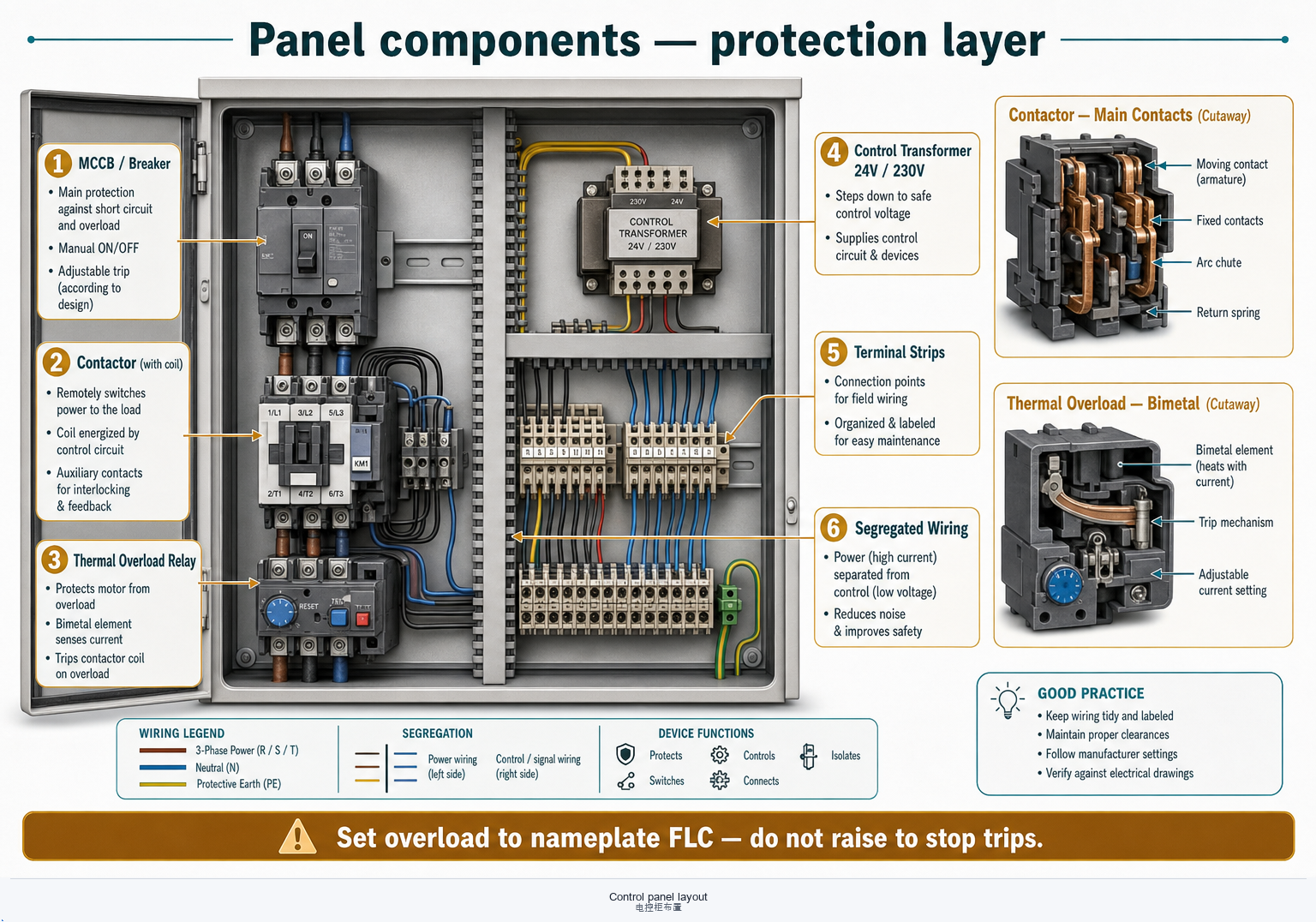
Contactors, breakers, thermal relays, and transformers are the physical layer under the software story. Cabinet layout and wiring practice decide whether the clever controller survives the first summer.
Contactors & motor starters
Size for FLC and utilization category; check coil voltage and auxiliary contacts used by interlocks. Welded contacts after repeated stall starts are a wiring or logic problem upstream.
Breakers & thermal relays
MCB/MCCB curves must discriminate with upstream supply protection. Thermal overlays (or electronic equivalents) protect motors—set to nameplate FLC, not “a bit higher so it stops tripping.”
Control transformers & supplies
24 V / 230 V control rails need headroom for coil inrush and PLC loads. Separate dirty VFD power from clean sensor supplies when the OEM calls for it.
Wiring & cabinet practice
Segregate power and signal, respect bend radii, label both ends, and keep IP and ventilation consistent with ambient. Flammable-refrigerant zones add enclosure and sparking-device rules—follow the OEM and code, not habit.
6 · AI assist, remote control & IoT
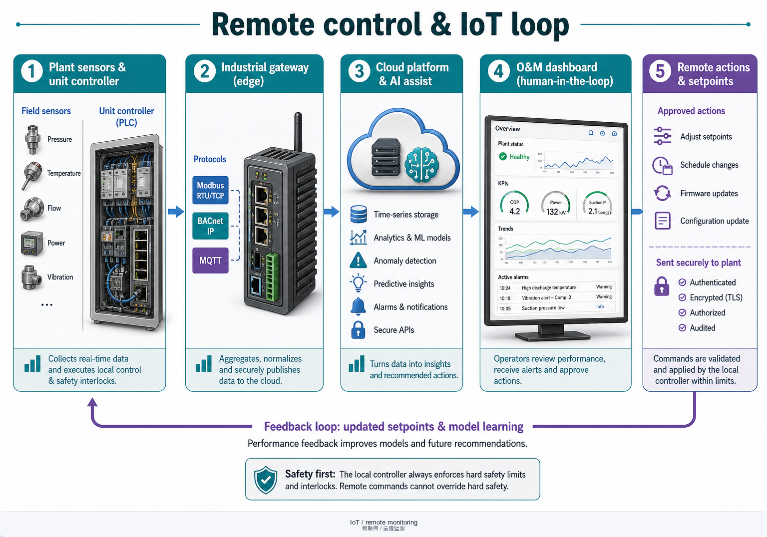
Edge and cloud layers can diagnose, forecast load, and suggest setpoints—but they sit on top of sensors, interlocks, and human accountability. Connectivity without cybersecurity and an O&M loop is just a new failure surface.
Diagnostics & load forecast
Pattern detection on currents, ΔT, and cycle counts can flag fouling or valve issues early. Load forecasts help staging—but they need site-specific training data, not a generic “AI efficiency” claim.
Optimization limits & human responsibility
Algorithms may trim setpoints within a band; they must not defeat frost protection, HP cut-out, or minimum flow. Keep a named responsible engineer for accepted recommendations.
Gateway, protocols & datapoints
Modbus, BACnet, MQTT, and proprietary buses need a point list: units, write masks, and poll rates. A gateway that drops quality bits turns remote monitoring into false confidence.
Cybersecurity & O&M loop
Segment networks, patch gateways, rotate credentials, and restrict write access. Alarms must reach people who can act—dashboard vanity metrics without a ticket path do not improve COP.
7 · Selection & integration checklist
Lock electrical supply, motor/VFD duty, and safety/IoT boundaries before comparing controller feature lists.
- Supply & drive: voltage, phases, short-circuit level, DOL vs soft start vs VFD; cable and harmonic budget.
- Motor & compressor match: insulation class, IP, inverter-duty rating aligned with the compressor map and oil-return limits.
- Protection chain: breaker curve, thermal/electronic overload, HP/LP and process interlocks wired as hard stops.
- Controller & sensors: I/O count, mode sequences (heat/cool/defrost), sensor types and placement assumptions.
- AI / remote write policy: which setpoints cloud or BMS may change; explicit ban on bypassing safety; named human owner.
- IoT & cybersecurity: protocol, datapoint list, gateway hardening, alarm-to-O&M path; keep vessels/valves process points consistent with vessels and valves guides.
Need OEM electrical and controls portals? Use Tools & Standards · links.
8 · Quick FAQs
“Does a VFD always raise seasonal COP?”
Often at part load—if oil return, minimum speed, and evaporator design support turndown. A VFD fighting chronic flood-back or a starved oil circuit can worsen reliability without delivering the brochure COP.
“Can I raise the thermal-relay setpoint to stop nuisance trips?”
No. Find the cause: wrong FLC setting, single-phasing, blocked condenser, or sticky contactor. Masking overload protection trades a trip for a burnt motor.
“Is cloud AI a substitute for on-site sensors and interlocks?”
No. Remote analytics need truthful local measurements and must respect hard safety. AI suggests; locked-out protection and licensed electrical practice decide.
“Where next on this site?”
Enclosure & cables · Vessels · Valves · Compressors · Fundamentals.
OEM application limits, panel schematics, and electrical-code editions vary by product and jurisdiction. This page is engineering orientation—not a substitute for manufacturer manuals, wiring diagrams, or licensed electrical design and inspection.