Heat pump basics · Valves
Valve knowledge guide
Valves govern superheat, flow direction, isolation, and safety relief. An electronic expansion valve is not “a more expensive TXV”—it is a control and diagnostics interface. This guide covers refrigerant-side families in depth, then one chapter on water-side hydronic valves so the two BOMs stay separate. Pair with heat exchangers and compressors; OEM links under Tools & Standards.
1 · Role in the vapor-compression cycle
Without controlled throttling and (on heat pumps) reversing, the cycle cannot hold the evaporator and condenser where you need them. Valve faults often present as compressor trips or odd frost patterns.
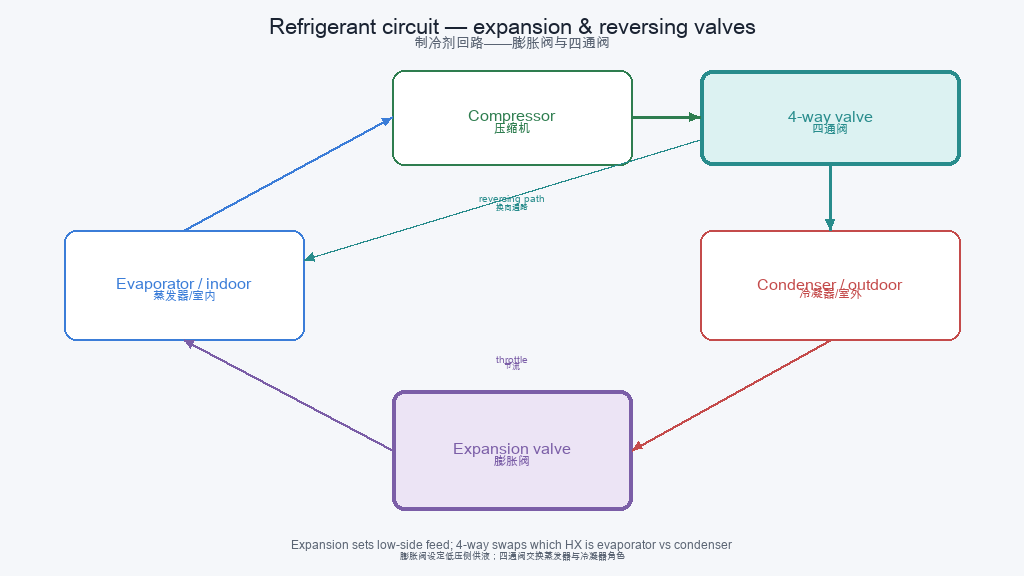
Throttle + meter
The expansion device drops pressure and meters mass flow so the evaporator can absorb heat at the right temperature. Capacity must match the compressor map at your duty—not a catalog orifice alone.
Direction & isolation
Reversing valves swap indoor/outdoor roles. Solenoids and shut-off valves protect pump-down, service, and charge boundaries.
Safety boundary
Relief / safety valves protect pressure vessels and piping. They are not modulating control valves—set pressure and discharge path follow code, not convenience.
2 · Refrigerant-side valve families
Use the family as a first filter: expansion, reversing, isolation, one-way, and relief each solve a different problem.
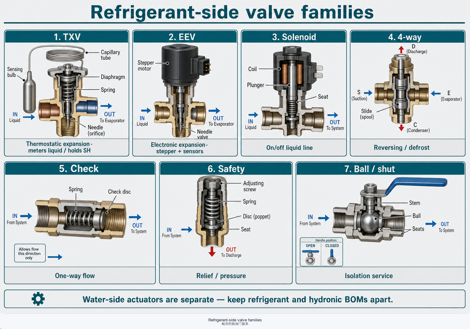
| Family | Primary job | Sensing / drive | Typical failure mode | Heat-pump intuition |
|---|---|---|---|---|
| TXV | Meter liquid; hold SH | Bulb + spring / diaphragm | Wrong charge; bulb placement | Stable commercial packs |
| EEV | Meter liquid; hold SH / maps | Stepper + P/T sensors | Debris; drive/firmware | Inverter HP mainstream |
| Solenoid | On/off liquid or hot gas | Coil energize | Stuck; leak-by | Pump-down / isolation |
| 4-way reversing | Swap evaporator/condenser | Pilot solenoid + slide | Stuck mid; internal bypass | Reversible A2W / A2A core |
| Check / shut-off / relief | One-way · isolate · relieve | Flow / manual / spring | Wrong orientation; misuse as control | Piping integrity & code |
Hot-gas bypass and electronic evaporator pressure regulators are specialty cousins—confirm OEM application notes before copying a comfort-HP BOM.
3 · Expansion valves in depth
Both TXV and EEV chase evaporator superheat. The difference is how they sense, actuate, and talk to the rest of the control system.
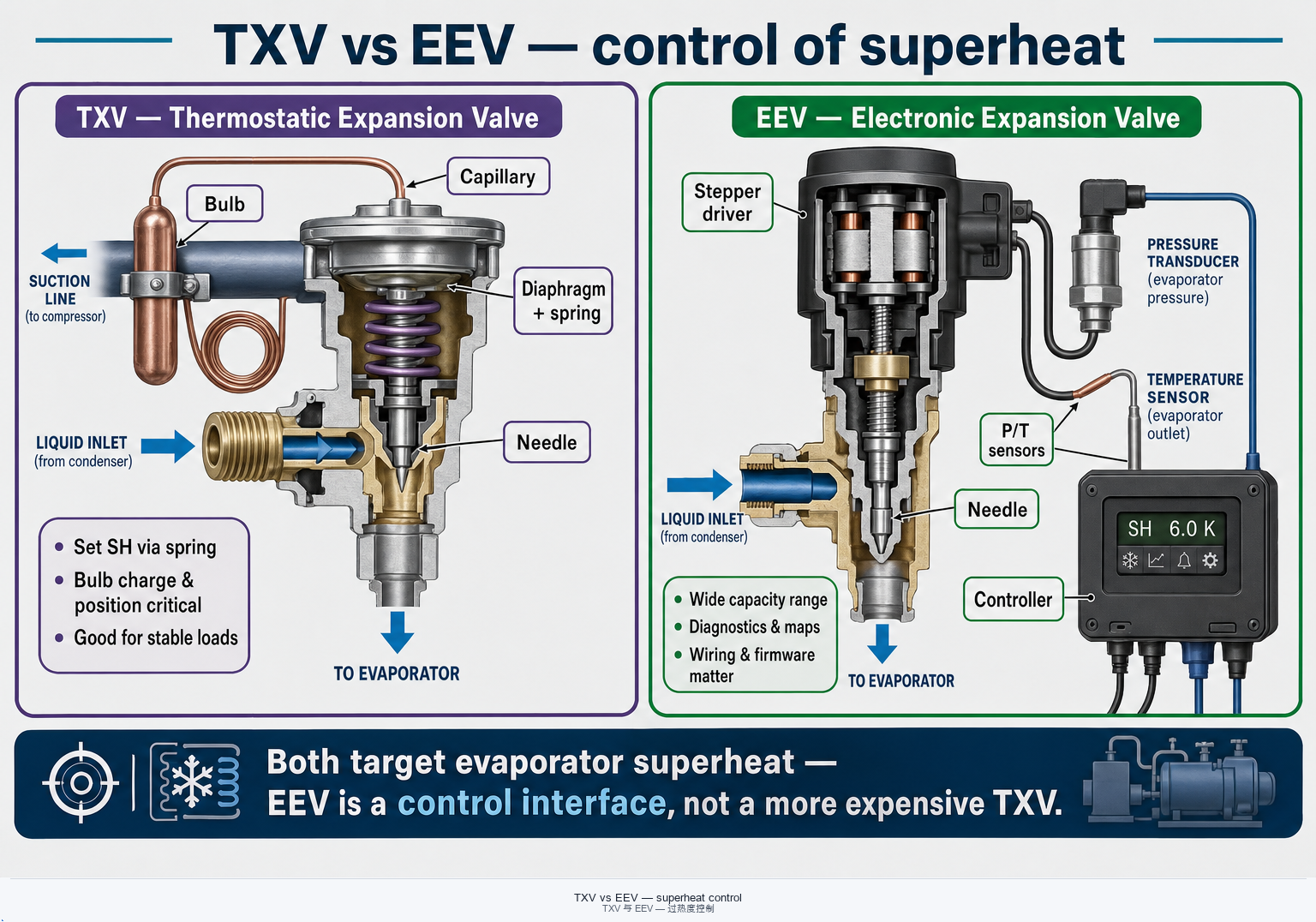
Superheat setpoint
Too low risks liquid flood-back; too high cuts capacity and raises discharge temperature. Align SH with the compressor map assumption.
TXV specifics
Bulb charge must match refrigerant and climate. Poor contact or wrong equalizer location creates hunting or chronic flood/starve.
EEV specifics
Wide turndown suits inverter compressors—but filter-driers, correct step counts, and firmware maps are part of selection. A stuck EEV is a system event, not a “bad compressor.”
Flash gas & capacity
Liquid line pressure drop and heat gain create flash gas before the valve—effective capacity falls. Size the valve for mass flow at the true inlet state.
4 · System valves and piping roles
Reversing, solenoids, checks, and bypass paths define mode changes and protection logic—not just “extra fittings.”
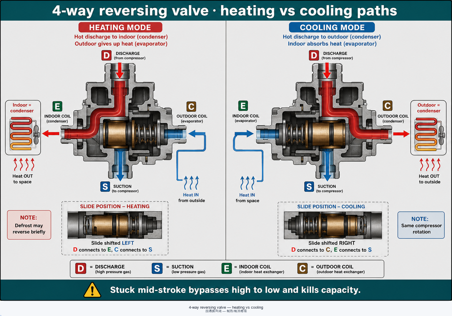
4-way & defrost
Confirm pilot logic, equalization time, and whether the compressor must stop or float during switch. Stuck mid-stroke bypasses high to low.
Liquid-line solenoid
Pump-down and off-cycle migration control often depend on a solenoid upstream of the expansion device. Leak-by refills the evaporator after stop.
Check valves & bypass
Checks enforce intended one-way paths in reversible and multi-HX plants. Hot-gas bypass is a capacity/pressure tool—apply only with OEM guidance.
Service isolation
Ball and shut-off valves enable recovery and repair. Cap seals and correct orientation matter for low-GWP and flammable fluids.
5 · Water-side valves (one chapter)
Hydronic valves live outside the refrigerant loop. Mixing their BOM with TXV/EEV language causes wrong seals, wrong codes, and wrong sizing.
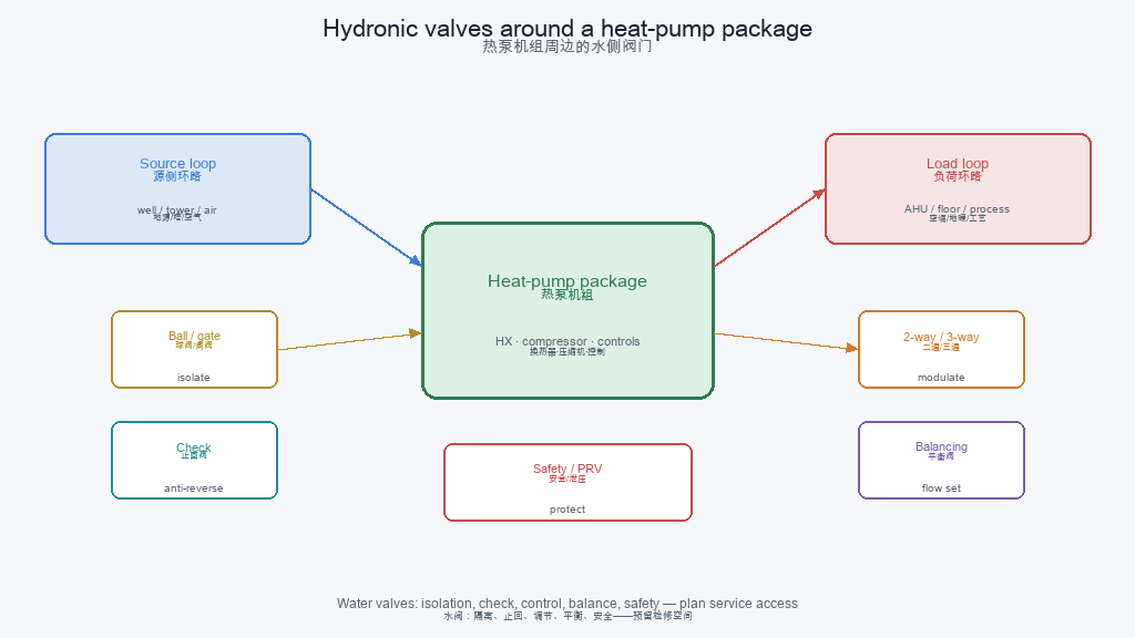
2-way / 3-way & mixing
Zone control and weather compensation often use motorized valves. Authority and ΔT design belong to the hydronic engineer.
Balancing & bypass
Commissioning valves set design flow. Differential-pressure or minimum-flow bypasses protect plate exchangers from freeze and laminar oil issues on the refrigerant side.
Water safety relief
Expansion vessels and relief valves handle water-side pressure—separate from refrigerant relief setpoints.
Keep the boundary clear
Quote and procure refrigerant valves and hydronic actuators on separate lines with separate standards references.
6 · Common faults and reliability
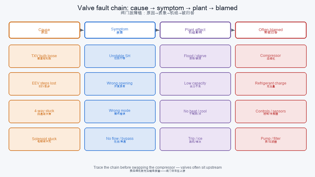
A useful diagnostic habit: cause → valve symptom → plant symptom → what gets wrongly blamed.
TXV / bulb issues
Loose bulbs, wrong charge, or poor insulation create hunting, flood-back, or chronic starve—symptoms that look like “bad HX” or “weak compressor.”
EEV blockage & drive
Moisture/debris and lost steps leave the valve stuck. Check filter-driers, coil resistance, and controller alarms before condemning the motor.
Reversing internal leak
Internal bypass equalizes pressures and kills capacity. Temperature and pressure on D/S/E/C ports tell the story faster than guessing.
Relief misuse
A chattering or weeping relief is a pressure or charge problem—or a wrong set pressure—not a modulating control opportunity.
7 · Selection checklist
Lock fluid, capacity, and control interface before comparing catalog prices.
- Refrigerant compatibility (and A2L / natural-fluid sealing / zoning notes).
- Capacity & ΔP range at design mass flow and liquid inlet state.
- Control interface: bulb vs sensors, stepper protocol, BMS points.
- Reversing / solenoid logic aligned with defrost and pump-down sequence.
- Safety relief set pressure and discharge path per code—not “closest stock.”
- Match the plant: same duty as HX and compressor maps; keep water valves on a separate line.
Need OEM catalogs and selection portals? Use Tools & Standards · links.
8 · Quick FAQs
“Why does an EEV system still frost heavily?”
Wrong SH target, sensor placement, airflow, or charge can still ice a coil. EEV does not repeal psychrometrics—check the outdoor HX frost chapter.
“How do I spot a stuck 4-way valve?”
Abnormal port temperatures/pressures, weak capacity in one mode, or equalized readings across ports. Confirm coil power and slide travel before swapping the compressor.
“Can a safety relief act as a control valve?”
No. Relief devices protect; modulating control needs a designed valve and setpoint strategy.
“Where next on this site?”
Heat exchangers · Compressors · Refrigerants · Fundamentals.
OEM application limits, seal materials, and code editions vary by product and jurisdiction. This page is engineering orientation—not a substitute for manufacturer manuals, PED/ASME practice, or licensed design.